Internal combustion engine and operating method therefor

a technology of internal combustion engine and operating method, which is applied in the direction of combustion engine, fuel injection apparatus, charge feed system, etc., can solve the problems of limiting the power output of the engine, inability to fully burn enough fuel per power stroke in the comparatively small cylinder of the more power dense engine, and failure to achieve the higher demand for fuel quantity

Inactive Publication Date: 2009-10-06
CATERPILLAR INC
View PDF24 Cites 17 Cited by
  • Summary
  • Abstract
  • Description
  • Claims
  • Application Information

AI Technical Summary

Benefits of technology

[0013]In another aspect, the present disclosure provides a method of operating an internal combustion engine, including a step of rotating an engine crankshaft via a plurality of pistons, each reciprocable a stroke distance within an engine cylinder and configured to increase a pressure therein to a pressure sufficient for compression ignition of fuel. The method further includes a step of injecting a liquid fuel into each of the cylinders via fuel injectors extending into each of the cylinders and having a plurality of outlet orifices. The method still further includes a step of burning fuel injected into each of the cylinders to yield at least about 150 horsepower per liter of engine displacement at a smoke output of less than about 0.4 grams smoke per horsepower-hour and a fuel consumption of less than about 250 grams fuel per kilowatt-hour output of the engine.

Problems solved by technology

However, attempts to scale down many internal combustion engines below certain limits have met with little success, particularly with regard to direct injection compression ignition engines.
Many smaller, theoretically more power dense engines may be incapable of fully burning sufficient fuel per each power stroke in their comparatively small cylinders to meet higher power demands.
For example, if a conventional engine is running at a lower temperature and boost, where relatively small fuel quantities are injected for each cycle, and more power is demanded of the engine, an inability to burn the higher demanded fuel quantities may limit the engine's power output.
This problem is particularly acute in smaller bore engines.
Wall wetting can thus limit small bore engines to lower power and worse emissions than what intuitively could be their inherent capabilities, as wall wetting tends to cause poor combustion and high hydrocarbon and particulate emissions.
Inadequate mixing of the fuel and air, however, can cause excessive smoke before combustion, limiting the engine's power long before its theoretical power limit is reached.
One reason for these limitations is that at higher RPMs, there is only a relatively small amount of time within which to inject and ignite fuel in each cylinder.
Higher speed compression ignition engines tend to experience this problem regardless of engine size.
However, neither type of engine is typically capable of providing an attractive power density commensurate with their size and weight.
Although the TKDI 600 is claimed to have certain applications, such as in a small unmanned aircraft, the available BMEP is relatively low, about 169 PSI and the engine is therefore somewhat limited in its total available power output and hence, power density.

Method used


Image

  • Internal combustion engine and operating method therefor
  • Internal combustion engine and operating method therefor
  • Internal combustion engine and operating method therefor

Examples


Embodiment Construction

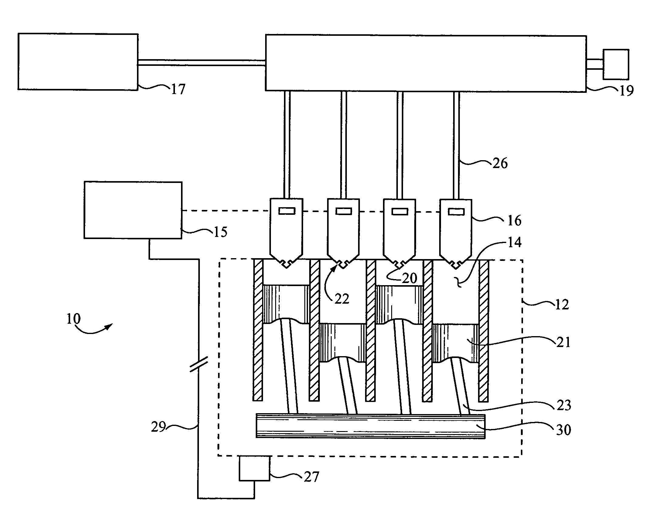
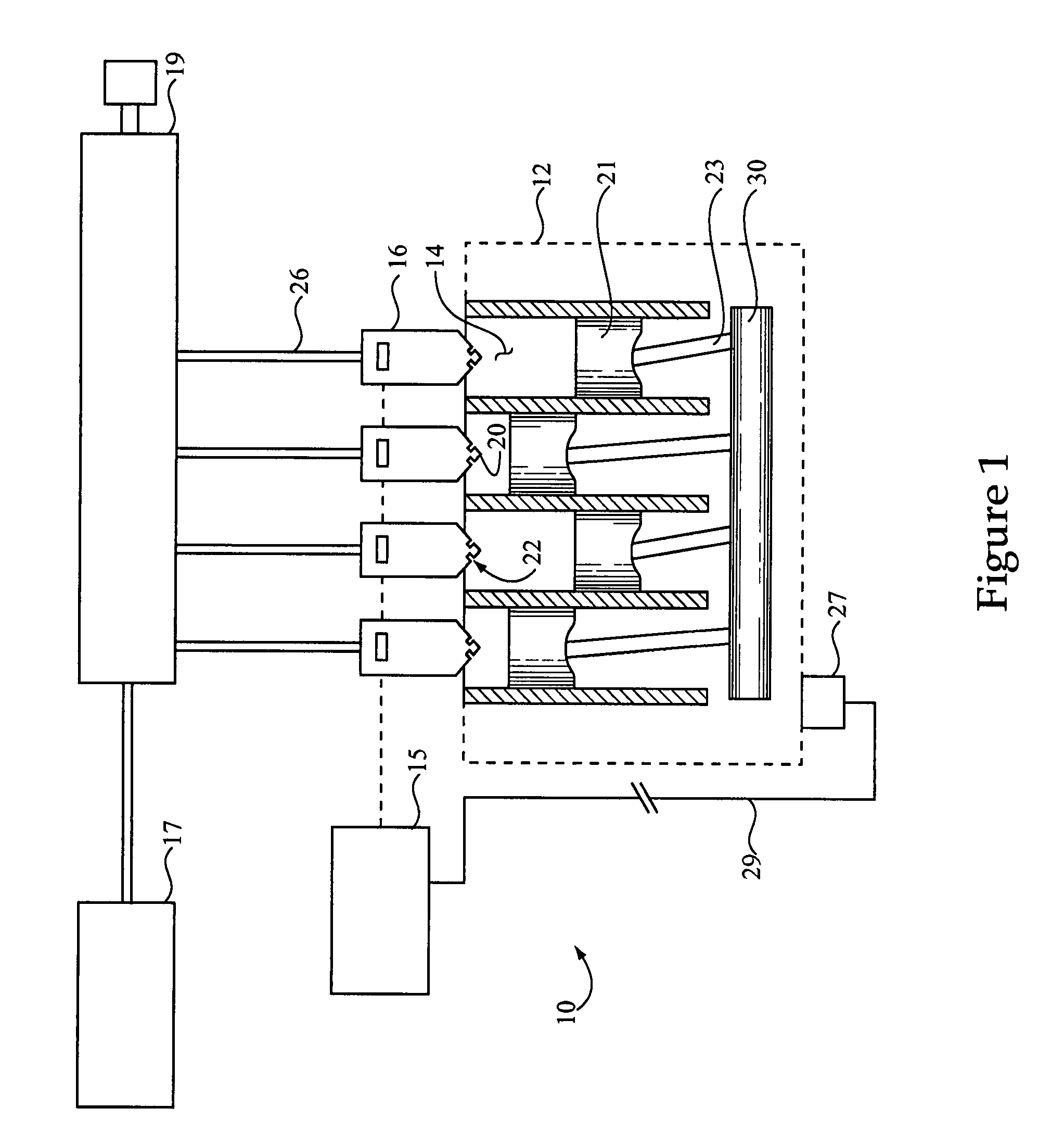
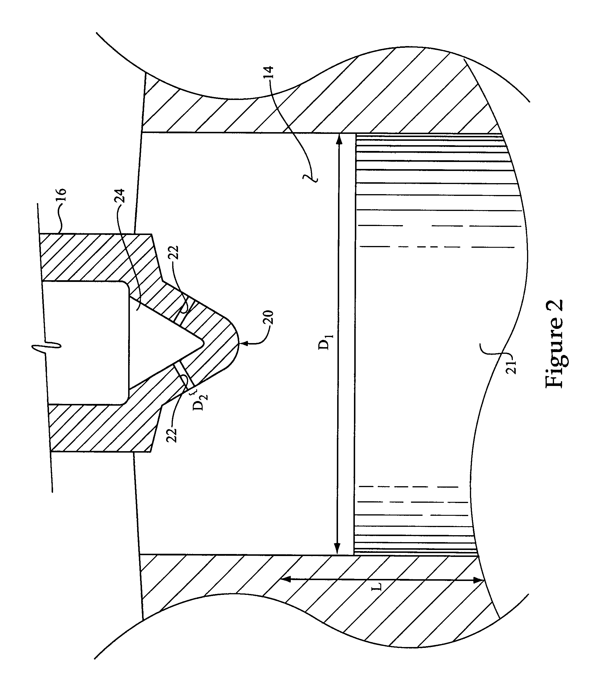
[0021]Referring to FIG. 1, there is shown a schematic illustration of an engine 10 according to one embodiment of the present disclosure. Engine 10 includes an engine housing 12 having a plurality of cylinders 14 therein. Fuel injectors 16 are disposed at fixed locations relative to housing 12, extend at least partially into each of cylinders 14 and are operable to direct inject a liquid fuel therein. Each of fuel injectors 16 may include a fuel injector tip 20 extending into the associated cylinder, each tip 20 having a plurality of outlet orifices 22. Engine 10 further includes a plurality of pistons 21, each disposed at least partially within one of cylinders 14 and movable therein to increase cylinder pressures to a pressure sufficient for compression ignition of fuel. The compression ratio may be up to about 15.5 to 1 in certain embodiments. Each piston is coupled with a crankshaft 30 via a piston rod 23 to enable rotation of crankshaft 30 via combustion of fuel in cylinders 14...


PUM


Abstract

The present disclosure provides an engine operating method and high power density internal combustion engine, including an engine housing with a plurality of cylinders. Fuel injectors are provided and disposed at least partially within each cylinder, and configured to inject fuel such as diesel, JP8 or another fuel therein for compression ignition. The engine is configured to burn a quantity of injected fuel to yield at least about 150 horsepower per liter of engine displacement at a smoke output of less than about 0.4 grams, and in some cases less than about 0.75 grams, smoke per horsepower-hour, at a fuel consumption of less than about 250 grams fuel per kilowatt-hour output of the engine.

Description

CROSS-REFERENCE TO RELATED APPLICATIONS[0001]This application is a continuation-in-part of U.S. patent application Ser. No. 11 / 076,339, filed Mar. 9, 2005 now U.S. Pat. No. 7,201,135.TECHNICAL FIELD[0002]The present disclosure relates generally to internal combustion engines, and relates more particularly to a high power density direct injection compression ignition engine and engine operating method.BACKGROUND[0003]Internal combustion engines have long been used as power sources in a broad range of applications. Internal combustion engines may range in size from relatively small, hand held power tools to very large diesel engines used in marine vessels and electrical power stations. In general terms, larger engines are more powerful, whereas smaller engines are less powerful. Engine power can be calculated with the following equation, where “BMEP” is brake mean effective pressure, the average cylinder pressure during the power stroke of a conventional four-stroke piston engine:Powe...

Claims


Application Information

Patent Timeline
Patent Type & Authority Patents(United States)
IPC IPC(8): F02B3/00F02M1/00
CPCF02B3/06F02B23/0642F02M61/1806F02B23/0672F02B23/0621F02B23/0624F02B23/0651Y02T10/123F02B23/0678F02B2275/14Y02T10/12Y02T10/125F02B25/04
Inventor VACHON, JOHN T.HERGART, CARL-ANDERS
Owner CATERPILLAR INC
Why Eureka
Try Eureka