
Imaging lens

a technology of imaging lens and lens body, applied in the field of imaging lens, can solve the problems of insufficient configuration, cost and compactness disadvantages of four-lens configuration, and achieve the effects of shortening the entire lens, reducing cost and compactness, and high aberration performan

Active Publication Date: 2009-10-06
TIANJIN OFILM OPTO ELECTRONICS CO LTD
View PDF13 Cites 8 Cited by
  • Summary
  • Abstract
  • Description
  • Claims
  • Application Information

AI Technical Summary

Benefits of technology

"The invention provides an imaging lens that has high performance with a compact configuration. The lens has a unique shape and layout of the lenses that satisfies certain conditions to achieve high performance. The lens has a small number of lenses, three in total, which makes it advantageous for shortening the overall length of the lens while correcting various aberrations. The lens also has a meniscus shape and a negative refractive power in the vicinity of the optical axis, which makes it easy to achieve sufficient back focus."

Problems solved by technology

In this case, an aspheric surface contributes to miniaturization and enhancement of performance but is disadvantageous in terms of ease of manufacture and likely to induce an increase in cost.
However, in terms of achievement of both imaging performance and compactness, the configuration is insufficient.
Moreover, by means of adoption of a four-lens configuration, performance can be enhanced when compared with the three-lens configuration, but the four-lens configuration is likely to become disadvantageous in terms of cost and compactness.

Method used


Image

  • Imaging lens
  • Imaging lens
  • Imaging lens

Examples


Embodiment Construction

[0049]Although the invention will be described below with reference to exemplary embodiments thereof, the following exemplary embodiments and modifications do not restrict the invention.

[0050]According to an exemplary embodiment of the present invention, an imaging lens has a lens configuration having the small number of lenses, three lenses as a whole, and the shapes of the respective lenses and the layout of the aperture diaphragm are appropriately set, and further the specific conditional expressions are satisfied. Consequently, a lens system of compact configuration exhibiting high aberration performance can be implemented.

[0051]Exemplary embodiments of the present invention will be described in detail hereunder by reference to the drawings.

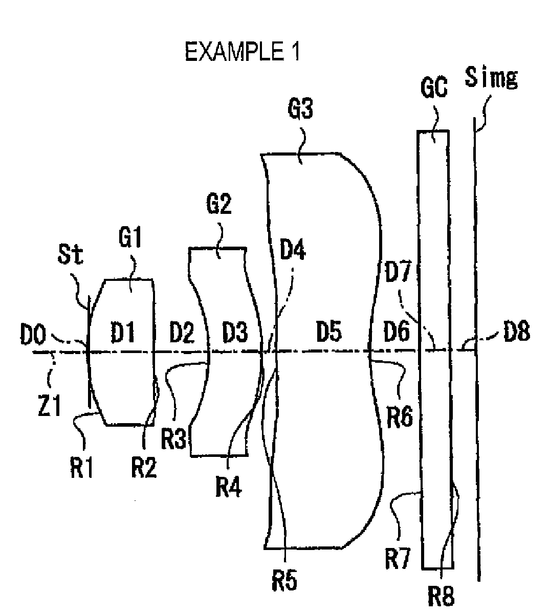
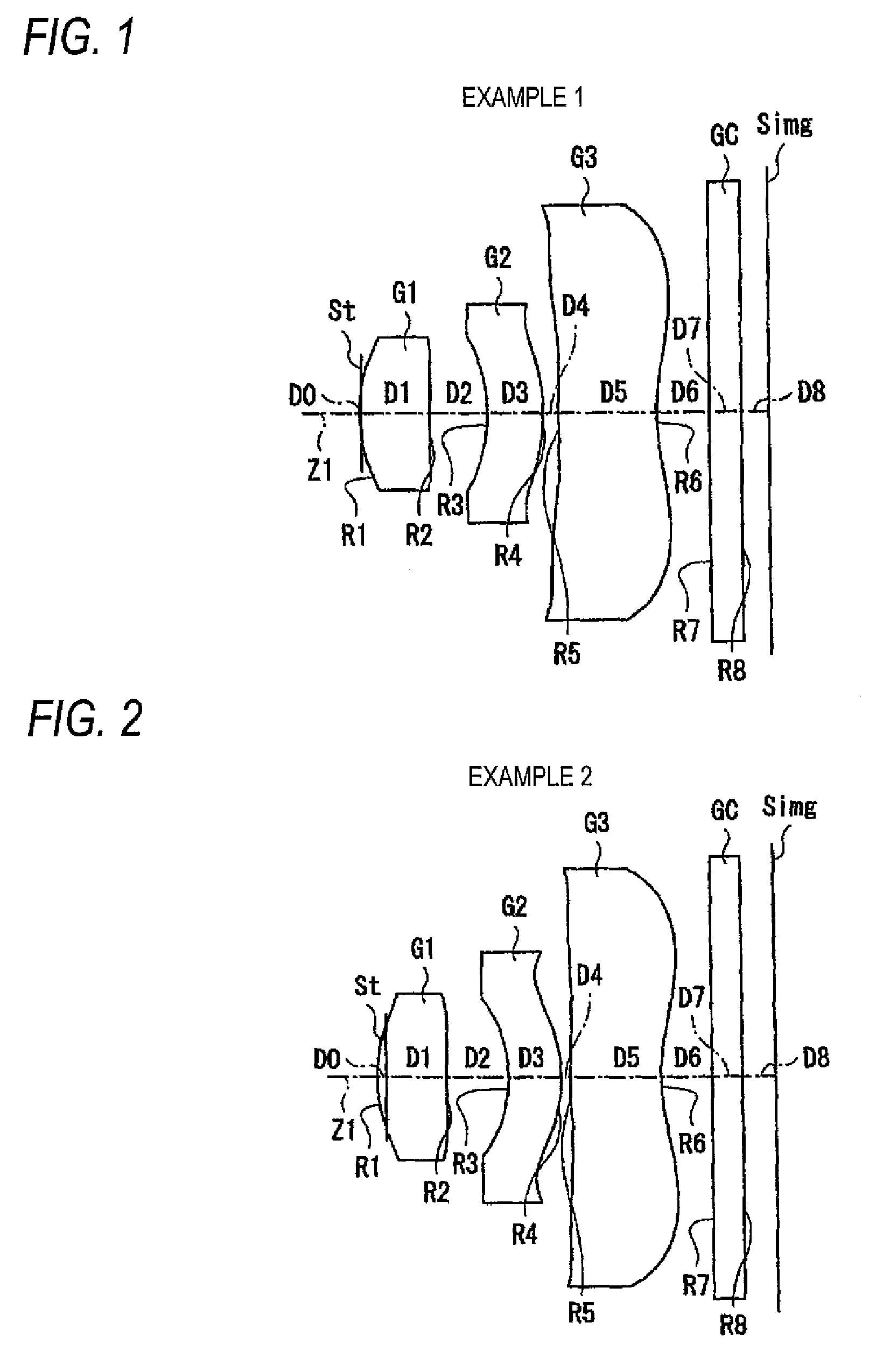
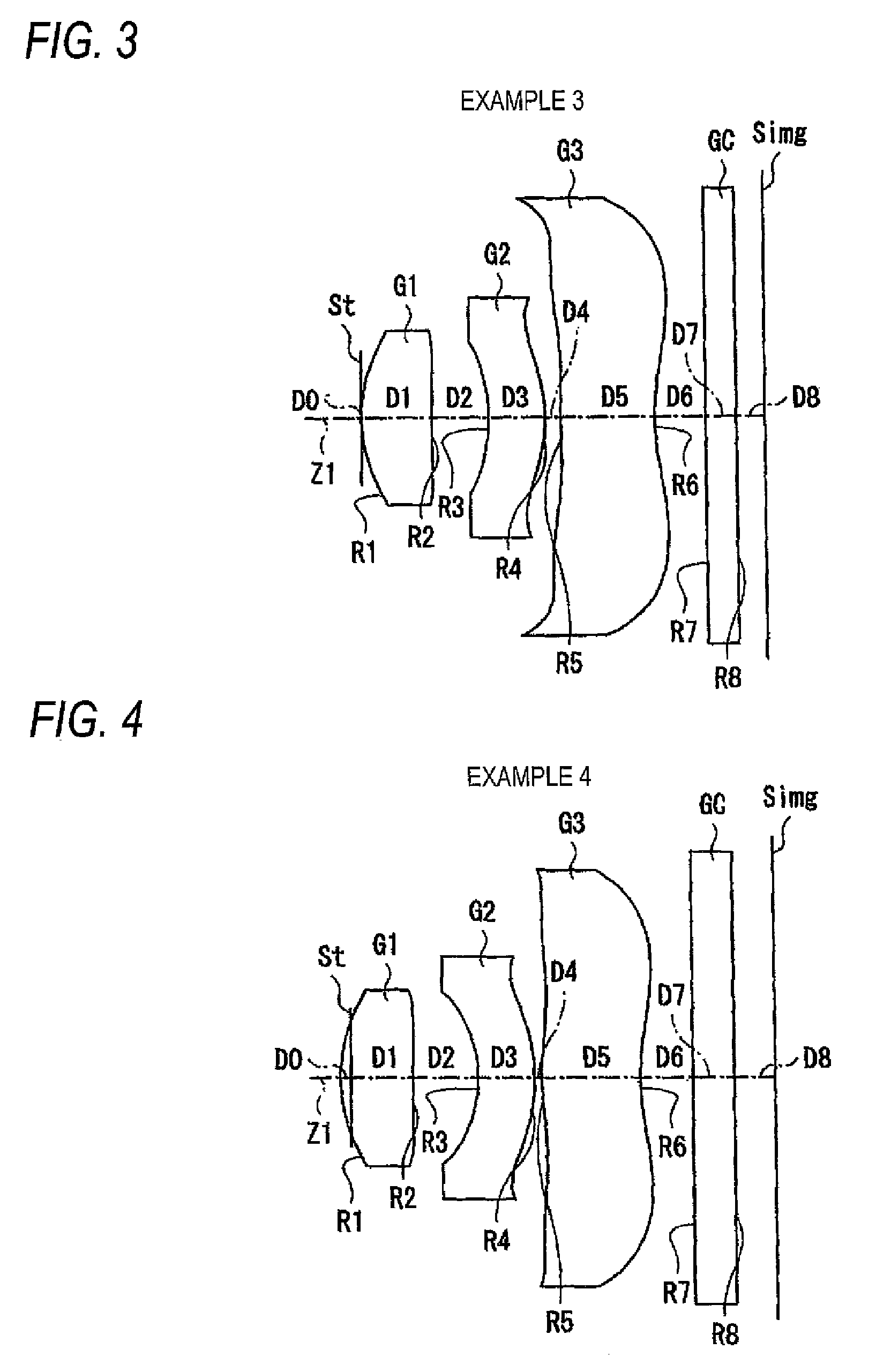
[0052]FIG. 1 shows a first configuration example of an imaging lens serving as an embodiment of the present invention. The configuration example corresponds to a lens configuration of a first numerical example (FIGS. 11A and 11B) to be descri...


PUM


Abstract

An imaging lens is provided and includes: in order from an object side of the imaging lens, an aperture diaphragm; a first lens having a positive refractive power and having a convex surface on the object side; a second lens having a negative refractive power and having a concave surface on the object side; and a third lens having a meniscus shape having a convex surface on the object side in the vicinity of an optical axis thereof, each of the first lens, the second lens and the third lens having at least one aspherical surface, and the imaging lens satisfying the following conditional expressions.0.9<|f2 / f|<11  (1)1.2<|f3 / f|<100  (2)f represents a focal length of the imaging lens; f2 represents a focal length of the second lens; and f3 represents a focal length of the third lens.

Description

BACKGROUND OF THE INVENTION[0001]1. Field of the Invention[0002]The present invention relates to an imaging lens having a fixed focal point, which is suitable for being incorporated into a digital camera using an imaging element, such as a CCD (Charge-Coupled Device) or CMOS (Complementary Metal Oxide Semiconductor), or a compact imaging device such as a camera using a silver film.[0003]2. Description of Related Art[0004]In step with recent popularization of personal computers into ordinary households, a digital still camera capable of inputting image information, such as a captured landscape or portrait, into a personal computer (hereinafter simply called a “digital camera”) has become quickly widespread. Moreover, there is an increase in the number of cases where a portable cellular phone is equipped with a module camera (a portable module camera) for inputting an image.[0005]An imaging element, such as CCD or CMOS, is used in these imaging devices. With a progress in miniaturizat...

Claims


Application Information

Patent Timeline
Patent Type & Authority Patents(United States)
IPC IPC(8): G02B9/12
CPCG02B9/12G02B13/18G02B13/0035
Inventor TANIYAMA, MINORU
Owner TIANJIN OFILM OPTO ELECTRONICS CO LTD
Learn More