
Self-regulating feedstock delivery systems and hydrogen-generating fuel processing assemblies and fuel cell systems incorporating the same

a fuel cell and self-regulating technology, applied in the direction of machines/engines, process and machine control, fluid pressure control, etc., can solve the problems of affecting the performance of the fuel cell stack and/or its ability to satisfy an application

Active Publication Date: 2009-10-13
DCNS SA
View PDF275 Cites 76 Cited by
  • Summary
  • Abstract
  • Description
  • Claims
  • Application Information

AI Technical Summary

Benefits of technology

"The present patent relates to fuel processing assemblies and fuel cell systems that produce hydrogen gas for various applications. The patent describes a fuel processing assembly with a feedstock delivery system that is designed to regulate the flow of feedstock to the hydrogen-producing region of the fuel processor. This system is important for ensuring the performance of the fuel cell system is not affected by changes in the flow rate of the feedstock. The patent also describes different variations of the fuel processing assembly and feedstock delivery system that can be used in fuel cell systems. The technical effects of the patent include improving the performance and efficiency of fuel cell systems by optimizing the flow rate of feedstock to the hydrogen-producing region of the fuel processor."

Problems solved by technology

When the flow rate of hydrogen gas to the fuel cell stack is affected by the flow rate of feedstock(s) to the hydrogen-producing region of the hydrogen-generation assembly, this may affect the performance of the fuel cell stack and / or its ability to satisfy an applied load thereto.

Method used


Image

  • Self-regulating feedstock delivery systems and hydrogen-generating fuel processing assemblies and fuel cell systems incorporating the same
  • Self-regulating feedstock delivery systems and hydrogen-generating fuel processing assemblies and fuel cell systems incorporating the same
  • Self-regulating feedstock delivery systems and hydrogen-generating fuel processing assemblies and fuel cell systems incorporating the same

Examples


Embodiment Construction

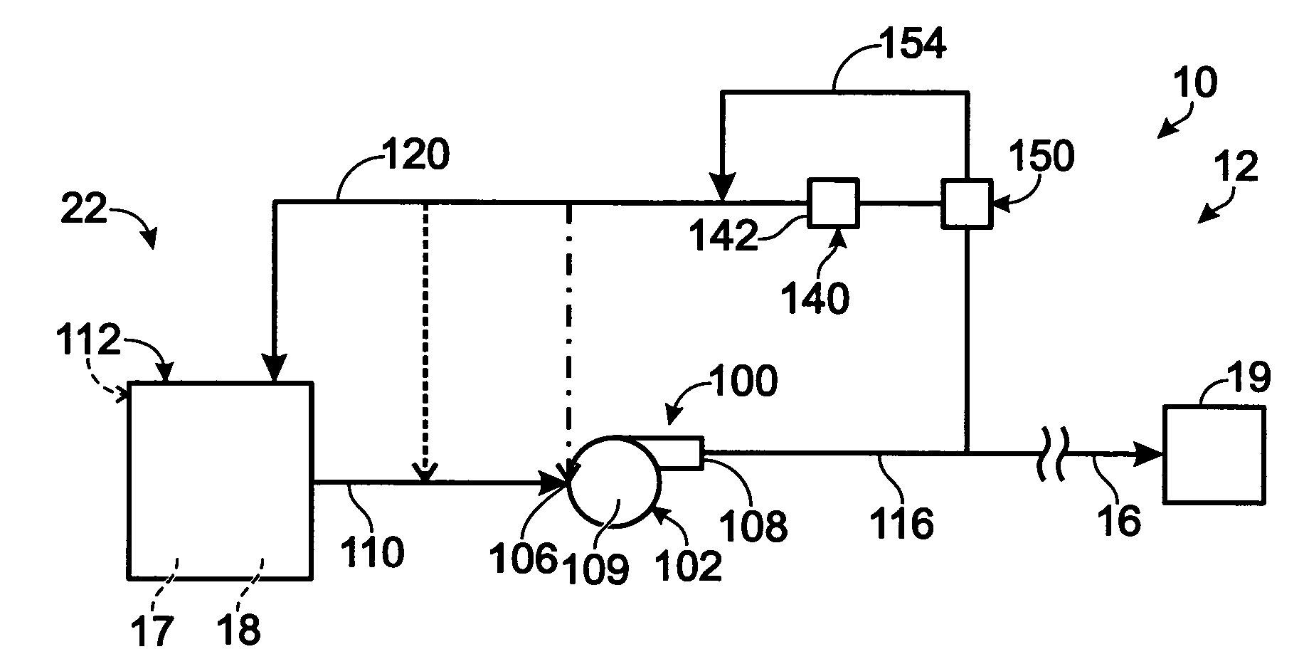
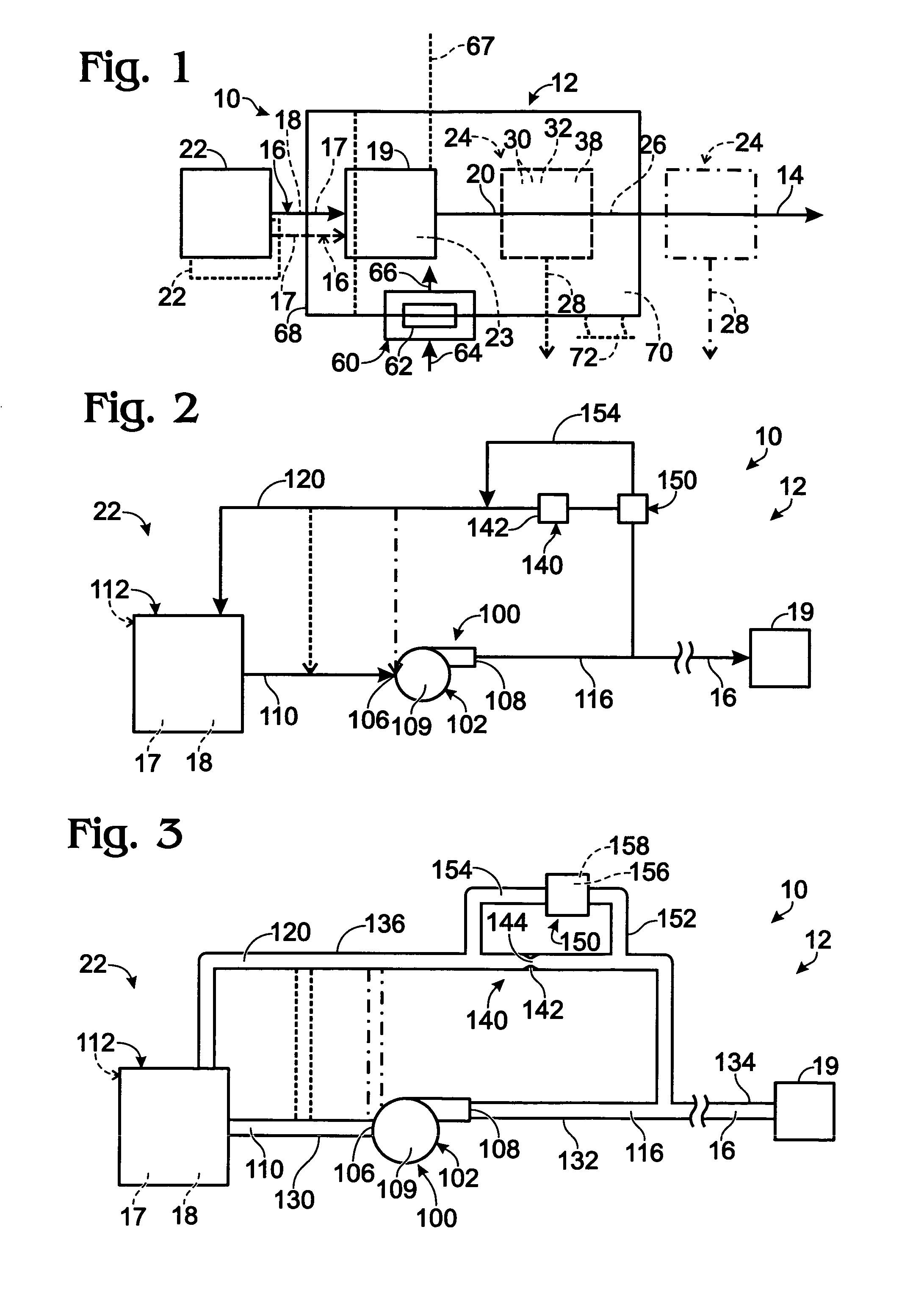
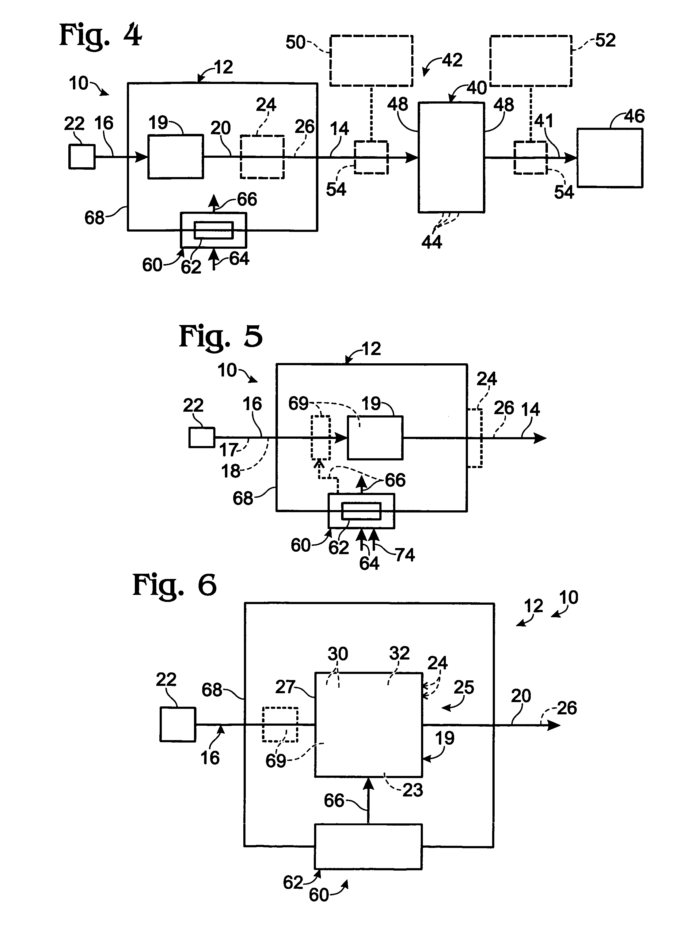
[0016]A fuel processing assembly containing a feedstock delivery system 22 according to the present disclosure is shown in FIG. 1 and is indicated generally at 10. Fuel processing assembly 10 includes a fuel processor 12 that is adapted to produce a product hydrogen stream 14 containing hydrogen gas, and preferably at least substantially pure hydrogen gas, from one or more feed streams 16. Feed stream 16 may include at least one carbon-containing feedstock 18. Fuel processor 12 includes any suitable device, or combination of devices, that is adapted to produce hydrogen gas from feed stream(s) 16. Accordingly, fuel processor 12 includes a hydrogen-producing region 19, in which an output stream 20 containing hydrogen gas is produced by utilizing any suitable hydrogen-producing mechanism(s). Output stream 20 includes hydrogen gas as at least a majority component. Output stream 20 may include one or more additional gaseous components, and thereby may be referred to as a mixed gas stream...


PUM

PropertyMeasurementUnit
pressureaaaaaaaaaa
vol %aaaaaaaaaa
vol %aaaaaaaaaa

Abstract

Feedstock delivery systems and hydrogen-producing fuel processing assemblies and fuel cell systems containing the same. The feedstock delivery systems include a liquid pump that draws at least one liquid feedstock from a supply and delivers at least one feed stream containing the feedstock(s) to a fuel processor, such as to the hydrogen-producing region thereof. The feedstock delivery system further includes a recycle conduit that establishes a fluid flow path for the liquid feedstock(s) from a location downstream of the pump back to a location upstream of the pump. In some embodiments, the feedstock delivery system further includes a flow restrictor associated with the recycle conduit and a pressure-actuated valve that selectively permits the recycled feedstock to bypass the flow restrictor. In some embodiments, the pump is configured to draw a greater flow rate of the feed stream from the supply than is delivered to the fuel processor.

Description

FIELD OF THE DISCLOSURE[0001]The present disclosure relates generally to hydrogen-producing fuel processing assemblies and fuel cell systems, and more particularly to feedstock delivery systems therefor.BACKGROUND OF THE DISCLOSURE[0002]Purified hydrogen gas is used in the manufacture of many products including metals, edible fats and oils, and semiconductors and microelectronics. Purified hydrogen is also an important fuel source for many energy conversion devices. For example, many fuel cells use purified hydrogen and an oxidant to produce an electrical potential. A series of interconnected fuel cells is referred to as a fuel cell stack, and this stack may be referred to as a fuel cell system when combined with sources of oxidant and hydrogen gas. Various processes and devices may be used to produce the hydrogen gas that is consumed by the fuel cells.[0003]A hydrogen-producing fuel processing assembly is an assembly of one or more devices or components that includes a fuel process...

Claims


Application Information

Patent Timeline
Patent Type & Authority Patents(United States)
IPC IPC(8): G05D7/00F17D3/00G05B9/00H01M8/18G05D16/00
CPCB01J8/0278C01B3/38C01B3/48H01M8/04201H01M8/0612Y02E60/50B01J2208/00539B01J2208/00548B01J2219/00191C01B2203/0233C01B2203/0244C01B2203/0261C01B2203/0283C01B2203/0405C01B2203/043C01B2203/044C01B2203/047C01B2203/0475C01B2203/0485C01B2203/0495C01B2203/066C01B2203/1217C01B2203/1223C01B2203/1229C01B2203/1241C01B2203/1247C01B2203/1252C01B2203/1647C01B2203/1685C01B2203/169B01J2208/00283
Inventor EDLUND, DAVID J.STUDEBAKER, R. TODD
Owner DCNS SA
Learn More