Boost converter

a converter and boost technology, applied in the field of boost converters, can solve the problems of reducing efficiency, bringing the extra burden of heat dissipation mechanism, and relatively expensive power switch components capable of sustaining high stress and low switching loss, and achieving low switching loss and low cos

Active Publication Date: 2009-10-13
ASUSTEK COMPUTER INC
View PDF51 Cites 15 Cited by
  • Summary
  • Abstract
  • Description
  • Claims
  • Application Information

AI Technical Summary

Problems solved by technology

Due to excessive current and switching loss, the power switch component 130 suffers from a great deal of dissipated heat, thus degrading effectiveness and bringing the extra burden of needing to incorporate a heat dissipation mechanism.
As a result, a relatively expensive power switch component capable of sustaining high stress and having low switching loss is needed herein.

Method used


Image

  • Boost converter
  • Boost converter
  • Boost converter

Examples


Embodiment Construction

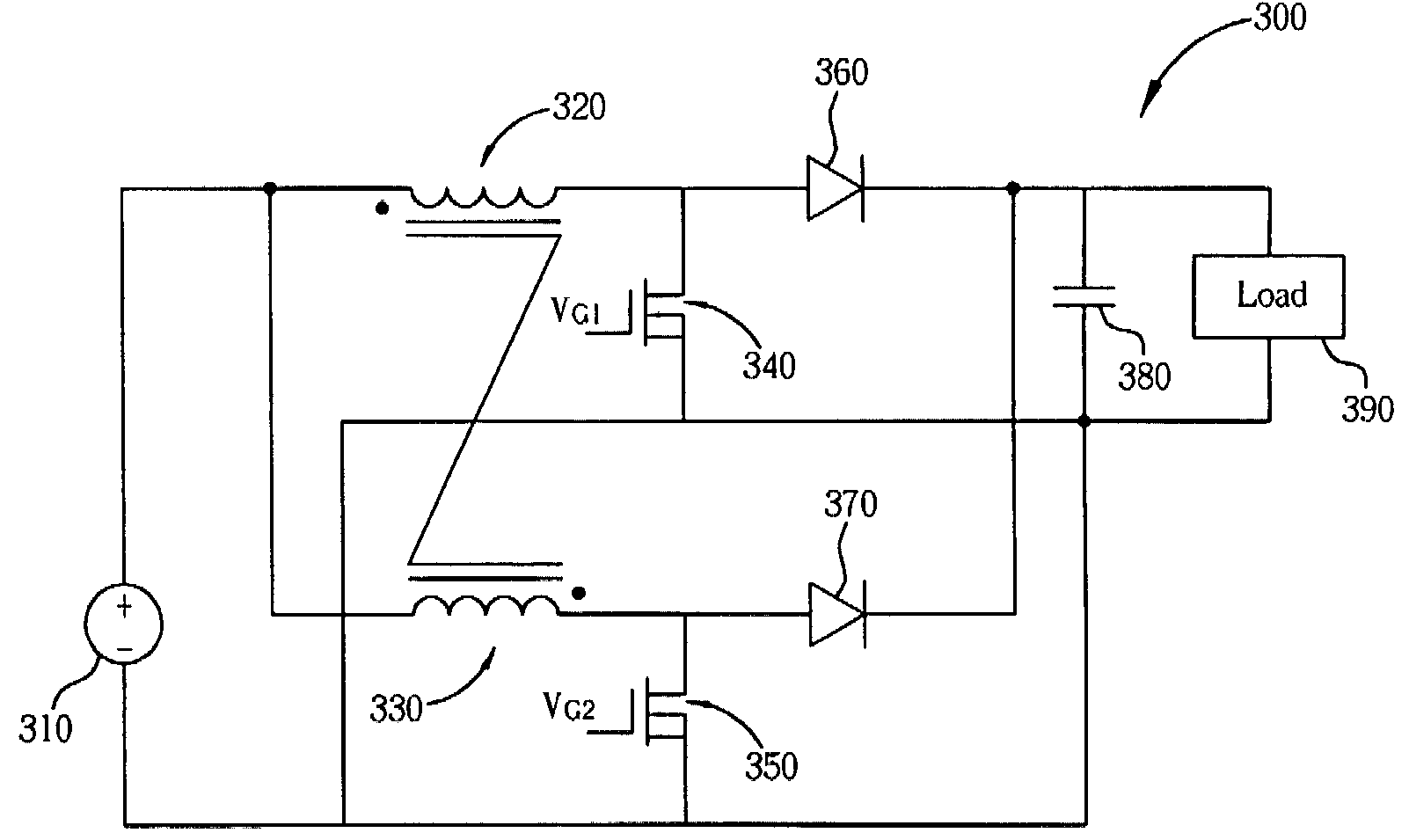
[0020]Please refer to FIG. 3. FIG. 3 is a circuit diagram of a boost converter 300 according to an embodiment of the present invention. In this embodiment, the boost converter 300 includes a voltage source 310, two conjugate coils 320 and 330, two power switch components 340 and 350, two switch components 360 and 370, and a filter 380. The voltage source 310 includes a first voltage level point and a second voltage level point, which can be a positive voltage output point and a negative voltage output point respectively in this embodiment. The negative voltage output point can also be regarded as a ground point. The two conjugate coils 320 and 330 are coils winding around the same core. Materials of the core can be air, or iron materials, where the iron materials can enhance mutual induction between the two conjugate coils 320 and 330. In this embodiment, the two conjugate coils 320 and 330 can be coils 320 and 330, for example. First coil ends of the coil 320 and the coil 330 are b...


PUM


Abstract

A boost converter includes a first boost conversion unit and a second boost conversion unit. Coils of the first boost conversion unit and the second boost conversion unit are coupled with each other. Due to coupling of the coils, the second boost conversion unit releases energy while the first boost conversion unit stores energy in a period of time. Furthermore, due to coupling of the coils, the first boost conversion unit releases energy while the second boost conversion unit stores energy in another period of time. The two boost conversion units operate alternately, thereby adjusting switching loss and averaging output power of components. Furthermore, as switching frequency increases, the coil inductance, as well as the capacitance required in the two boost conversion units can be reduced correspondingly, thus substantially enhancing responses of the two boost conversion units as a whole.

Description

BACKGROUND OF THE INVENTION[0001]1. Field of the Invention[0002]The invention generally relates to a boost converter, and more particularly, to a boost converter utilizing coupled coils.[0003]2. Description of the Prior Art[0004]A boost converter is a periodically switching converter commonly used for boosting voltage and adjusting power factor in circuits. FIG. 1 is a circuit diagram of a conventional boost converter 100. The boost converter 100 includes a voltage source 110, an inductor 120, a power switch component 130, a diode 140, a capacitor 150, and a load 160. A gate terminal G of the power switch component 130 is controlled by a pulse width modulation (PWM) signal. Furthermore, a turn-on time for the power switch component 130 in a period is controlled by modulating a duty cycle of the PWM signal. When the power switch component 130 is turned on, the voltage source 110, the inductor 120, and the power switch component 130 form a closed loop, and thus current I1 flowing thro...

Claims


Application Information

Patent Timeline
Patent Type & Authority Patents(United States)
IPC IPC(8): G05F1/46
CPCH02M3/1584
Inventor WENG, HSIANG-CHUNGCHENG, CHING-FUHUNG, HSIANG-JUIYANG, SUN-CHEN
Owner ASUSTEK COMPUTER INC
Why Eureka
Try Eureka