Moving dielectric, capacitive position sensor configurations

Inactive Publication Date: 2009-10-13
P I ENG
View PDF30 Cites 21 Cited by
  • Summary
  • Abstract
  • Description
  • Claims
  • Application Information

AI Technical Summary

Benefits of technology

[0015]In broad and general terms, this invention resides in a capacitive sensor configuration which is capable of determining position and/or velocity for rotary or linear translation using a movable dielectric coupled to an elongate member. In contrast to existing devices which u

Problems solved by technology

One problem with potentiometer-based joysticks and other input devices is that the potentiometers are relatively expensive and include moving parts that may become dirty or worn, resulting in intermittent behavior.
Although the result is a simple physical

Method used


Image

  • Moving dielectric, capacitive position sensor configurations
  • Moving dielectric, capacitive position sensor configurations
  • Moving dielectric, capacitive position sensor configurations

Examples


Example

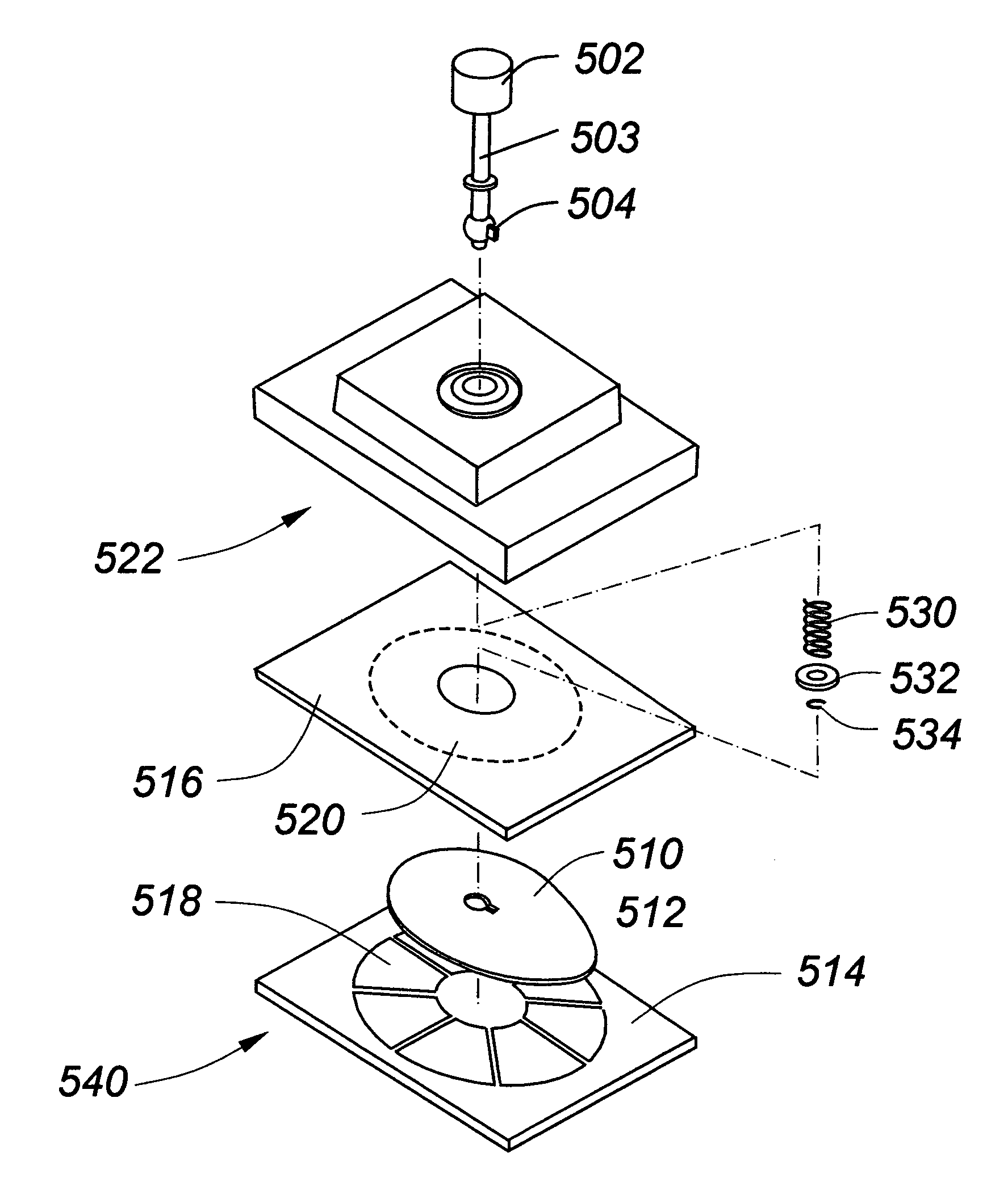
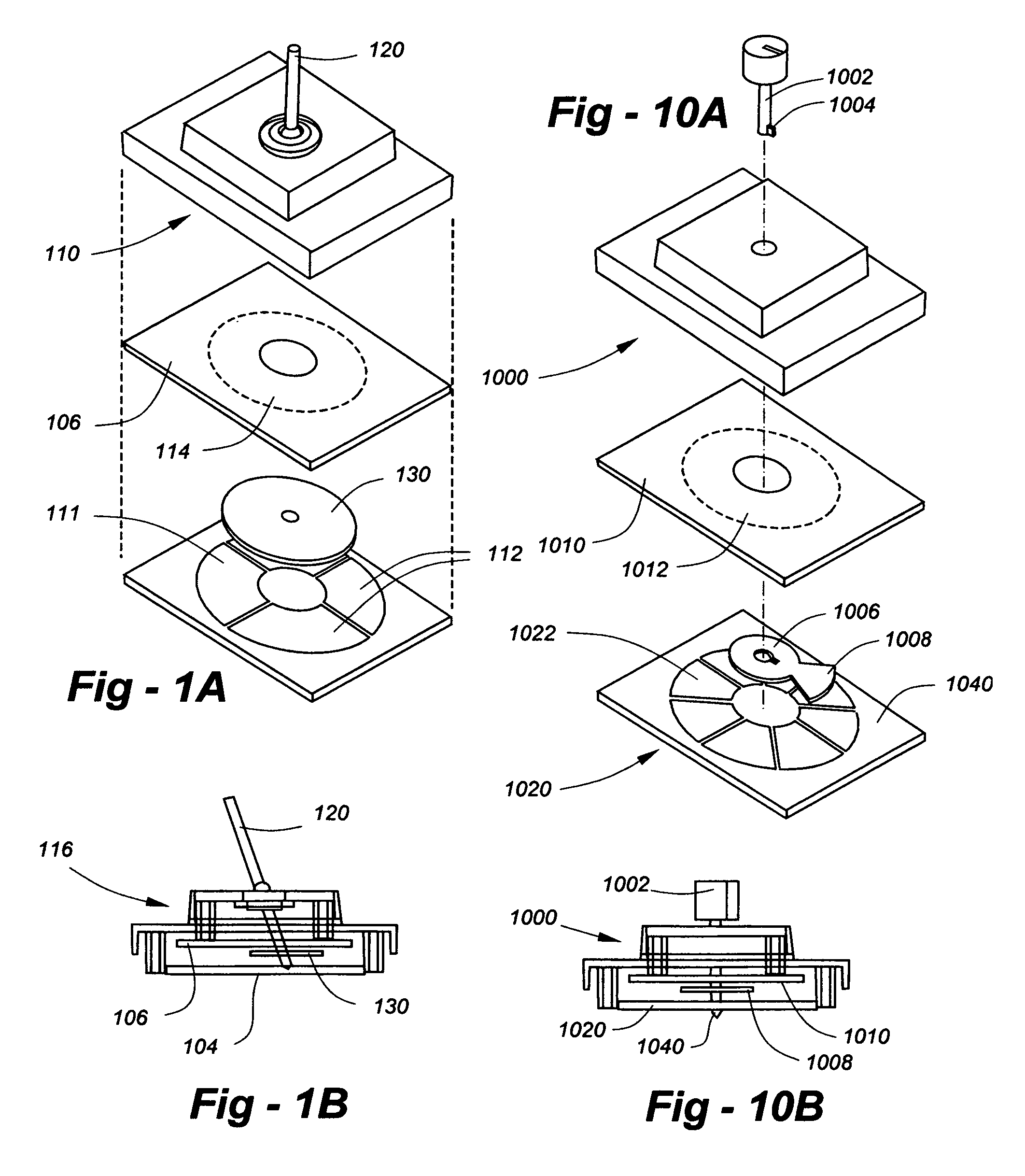
[0041]The capabilities of the invention will be illustrated with respect to the joystick depicted in FIGS. 1A and 1B, with the understanding that the technology is applicable to various other device types. The joystick of FIG. 1 is preferably constructed with an upper plate and a lower plate mounted in a housing such as a plastic case 110. The plates are preferably formed using metallization patterns on printed-circuit boards (PCBs). A lower PCB 104 incorporates transmitting metallization 111 on its upper surface. The transmitting metallization 112 is preferably separated into a plurality of sections 112 as needed for accuracy and / or speed in detecting of the position of the joystick lever 120. An upper PCB 106 preferably features a continuous or unbroken metalization pattern 114 on its lower surface. Alternatively, the upper plate 106 may be segmented, with the metalization of the lower PCB 104 being undivided.

[0042]When the upper and lower circuit boards 104, 106 are mounted in th...


PUM


Abstract

A capacitive sensor configuration is capable of determining position and/or velocity for rotary or linear translation using a movable dielectric element coupled to an elongate member. The dielectric element is supported between at least one detection plate and a plurality of transmitting plates. By measuring the charge on the detecting plate, the capacitances of the assembly at a given point in time can be determined, and this measurement is used to solve for position of the member. The dielectric need not be rigid, and the dielectric's distance from the plates does not have to be tightly controlled. The apparatus can be used to measure the position or velocity of a variety of devices, including computer peripherals such as mice, keyboards, joysticks, and other input control panels and pointing devices.

Description

REFERENCE TO RELATED APPLICATION[0001]This application claims priority from U.S. provisional patent application Ser. No. 60 / 183,997, filed Feb. 22, 2000, the entire contents of which are incorporated herein by reference.FIELD OF THE INVENTION[0002]This invention relates generally to position sensors, including computer input devices such as joysticks and, in particular, to a capacitive position sensor which incorporates a moving dielectric.BACKGROUND OF THE INVENTION[0003]Joysticks for use as computer input devices have been available for over two decades. To facilitate operation in two directions, a popular electromechanical configuration employs orthogonal potentiometers physically coupled to a moveable element. As one example of many, U.S. Pat. No. 4,156,130 describes a joystick mechanism for transducing vector motion of an end of a joystick into its X and Y components. The apparatus includes X- and Y-potentiometers, each having a body and a shaft, a rod connecting the shaft of t...

Claims


Application Information

Patent Timeline
IPC IPC(8): G09G5/08
CPCG05G1/04G05G1/08G05G9/047G06F3/0362G06F3/0338G06F3/03543G06F3/03548G05G2009/0474
Inventor HETHERINGTON, JACK H.
Owner P I ENG
Why Eureka
Try Eureka