Current density impedance imaging (CDII)

a technology of impedance imaging and current density, which is applied in the field of noninvasive mapping, can solve the problems of inability to use global methods, inability to widely accept eit as a clinical imaging tool, and inability to accurately represent the conductivity of the body, etc., and achieve the effect of accurate tissue conductivity distribution and high conductivity

Active Publication Date: 2009-10-13
NACHMAN ADRIAN +3
View PDF17 Cites 20 Cited by
  • Summary
  • Abstract
  • Description
  • Claims
  • Application Information

AI Technical Summary

Problems solved by technology

Although numerous surface electrodes (sometimes hundreds) are used during the procedure, EIT suffers from an inherent low spatial resolution due to the ill-posed nature of the problem.
Therefore, EIT has not been widely accepted as a clinical imaging tool.
Therefore, these global methods fail when there are areas of missing information inside the object (FIG. 1a on right).

Method used


Image

  • Current density impedance imaging (CDII)
  • Current density impedance imaging (CDII)
  • Current density impedance imaging (CDII)

Examples


embodiment

Preferred Embodiment

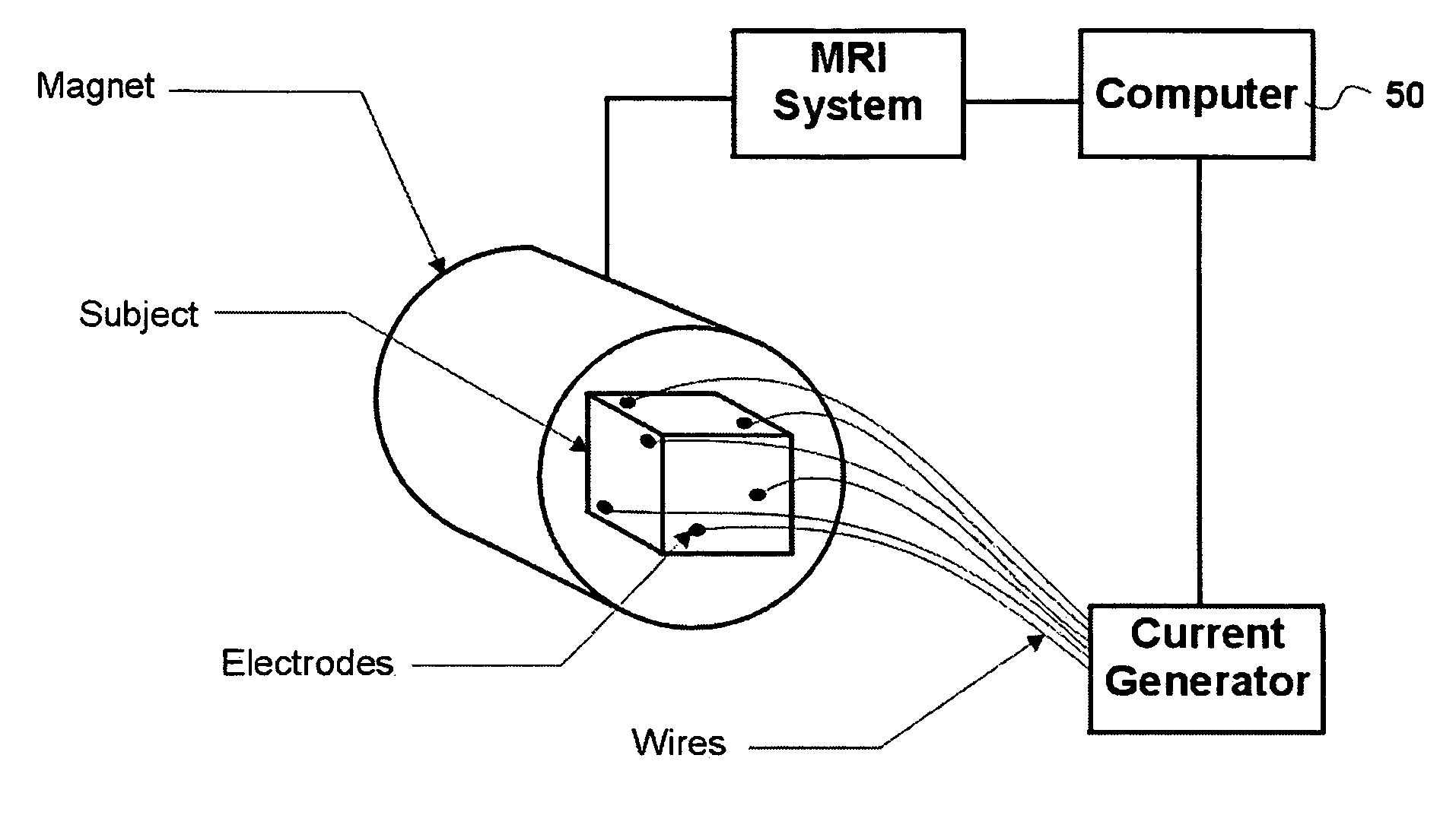
[0051]The current density vector information can be acquired using any current measurement techniques. Presently, the preferred method is to use the current density imaging (CDI) technique which utilizes a magnetic resonance imager to measure current density at all points within the object.

[0052]FIG. 4a shows a block diagram of the current density imaging (CDI) technique described in G. C. Scott, M. L. G. Joy, R. L. Armstrong, and R. M. Henkelman, “Measurement of nonuniform current density by magnetic resonance,”IEEE Trans. Med. Imag, vol. 10, pp. 362-374, 1991 which utilizes a magnetic resonance imager to measure current density at points within the object. The CDI system is set up by placing two or more electrodes on the surface of the object. For the present application, the current electrodes can be placed anywhere on the object as long as at least two sets of nonparallel current distributions can be created inside the object. All wires connecting to the elec...


PUM

PropertyMeasurementUnit
pore sizeaaaaaaaaaa
Larmor frequencyaaaaaaaaaa
electrical impedanceaaaaaaaaaa

Abstract

A method for non-invasive mapping (imaging) of the electrical impedance of an object. The present invention provides a method, current density impedance imaging (CDII) which produces an impedance image of object by measuring current density distributions and directly calculating the local impedance values. The method includes making measurements of at least two current density vector fields, J1 and J2, within a region of interest in an object and then calculating the logarithmic gradient of local conductivity, ∇ ln σ(x,y,z), using a formula∇ln⁢⁢σ=⁢(∇×J2)·(J1×J2)J1×J22⁢J1+⁢(∇×J1)·(J2×J1)J1×J22⁢J2+⁢(∇×J1)·J2J1×J22⁢J1×J2(1)where {right arrow over (J)}1(x,y,z) and {right arrow over (J)}2(x,y,z), are the pair of measured nonparallel current densities at point (x,y,z) and ∇ denotes the gradient operator.

Description

CROSS REFERENCE TO RELATED U.S. PATENT APPLICATIONS[0001]This patent application claims the priority benefit from U.S. Provisional Patent Application Ser. No. 60 / 499,734 filed on Sep. 4, 2003 entitled Current Density Impedance Imaging (CDII), and which is incorporated herein in its entirety.FIELD OF INVENTION[0002]The present invention relates to a non-invasive mapping (imaging) of the electrical impedance of an object.BACKGROUND OF THE INVENTION[0003]Electrical impedance tomography (EIT) is a technique that maps (images) the electrical impedance of an object non-invasively. EIT calculates internal impedance (or conductivity) of the object by applying a known electric current through its surface and then measuring the resulting surface potentials. Although numerous surface electrodes (sometimes hundreds) are used during the procedure, EIT suffers from an inherent low spatial resolution due to the ill-posed nature of the problem. Therefore, EIT has not been widely accepted as a clini...

Claims


Application Information

Patent Timeline
Patent Type & Authority Patents(United States)
IPC IPC(8): A61B5/05A61B5/053G01N27/02G01R27/02G01R33/20
CPCA61B5/0536
Inventor NACHMAN, ADRIANJOY, MICHAEL L. G.HASANOV, KARSHI F.YOON, RICHARD S.
Owner NACHMAN ADRIAN
Why Eureka
Try Eureka