Glove box device

a glove box and glove technology, applied in the direction of mechanical control devices, keyhole guards, instruments, etc., can solve the problems of affecting the operation of the glove box, the operation delay in transmitting the operational force, and the rapid accumulation of operational load, so as to prevent the generation of chattering sound and suppress the chattering of the slide member

Inactive Publication Date: 2009-10-20
HONDA LOCK MFG CO LTD
View PDF24 Cites 40 Cited by
  • Summary
  • Abstract
  • Description
  • Claims
  • Application Information

AI Technical Summary

Benefits of technology

[0008]Accordingly, it is an object of the present invention to provide a glove box device, wherein the number of components is reduced to simplify the structure thereby reducing the cost and improving the operational feeling, and moreover a gap between a design face of an operating handle and a cylinder lock is reduced thereby improving the appearance.
[0010]With the first feature, the cylinder of the cylinder lock is fixed to the operating handle, and hence the gap between the design face of the operating handle and the cylinder lock is reduced to improve the appearance. Moreover, when the rotor of the cylinder lock is in the unlocking state, the turning force of the rotor of the cylinder lock turning along with the operating handle is transmitted through the connecting member to the slide member, thereby bringing the locking mechanism into the unlocking state; and when the rotor is in the locking position, the turning force of the rotor of the cylinder lock turning along with the operating handle is not transmitted through the connecting member to the slide member. Therefore, only the connecting member serves as a component for transmitting the turning operation force of the operating handle to the slide member, thereby decreasing the number of the components and simplifying the structure, leading to the cost reduction. Further, no operational delay is generated in transmitting the operational force of the operating handle to the locking mechanism, thereby improving the operational feeling.
[0012]With the second feature, in a simple structure in which the driving abutment face and the abutment avoiding recess are provided on the outer surface of the rotor, the driving abutment face abutting against the one end of the connecting member when the rotor is in the unlocking position, the abutment avoiding recess being designed to avoid abutment against the one end of the connecting member when the rotor is in the locking position, the transmission and the cutting-off of the transmission of the turning force of the operating handle to the slide member is switched over in response to the unlocking and locking operations of the cylinder lock. Moreover, in the closed state of the lid, the other end of the connecting member is sandwiched between the one end of the slide member biased by the return spring to the locking operation position and the restricting portion provided in the base member, so that the slide member and the connecting member are pushed against the restricting portion of the base member by the action of the spring force of the return spring, thereby suppressing the chattering of the slide member and the connecting member to prevent the generation of chattering sound.

Problems solved by technology

However, in the glove box device disclosed in the Japanese Patent Application Laid-open No. 2004-76449, the transmission mechanism comprises a large number of components and also the structure is complicated, resulting in that the cost is liable to increase.
Further, the operation is delayed in transmitting the operational force of the operating handle due to the large number of components, whereby an operational load is quickly built up.
In addition, because the cylinder lock is mounted on the stationary portion separate from the operating handle, if a tip end of the cylinder lock is arranged to face a design face of the operating handle in its closing position, a misalignment is liable to be generated between the design face of the operating handle and the tip end of the cylinder lock.
Moreover, because it is required to provide a large opening in the design face in order to avoid the interference during operation of the operating handle, a gap is liable to be conspicuous.
Therefore, in the conventional device, it is necessary to contrive a measure for improving the dimensional accuracy of each part so that the gap is inconspicuous to the utmost.

Method used


Image

  • Glove box device
  • Glove box device
  • Glove box device

Examples


Embodiment Construction

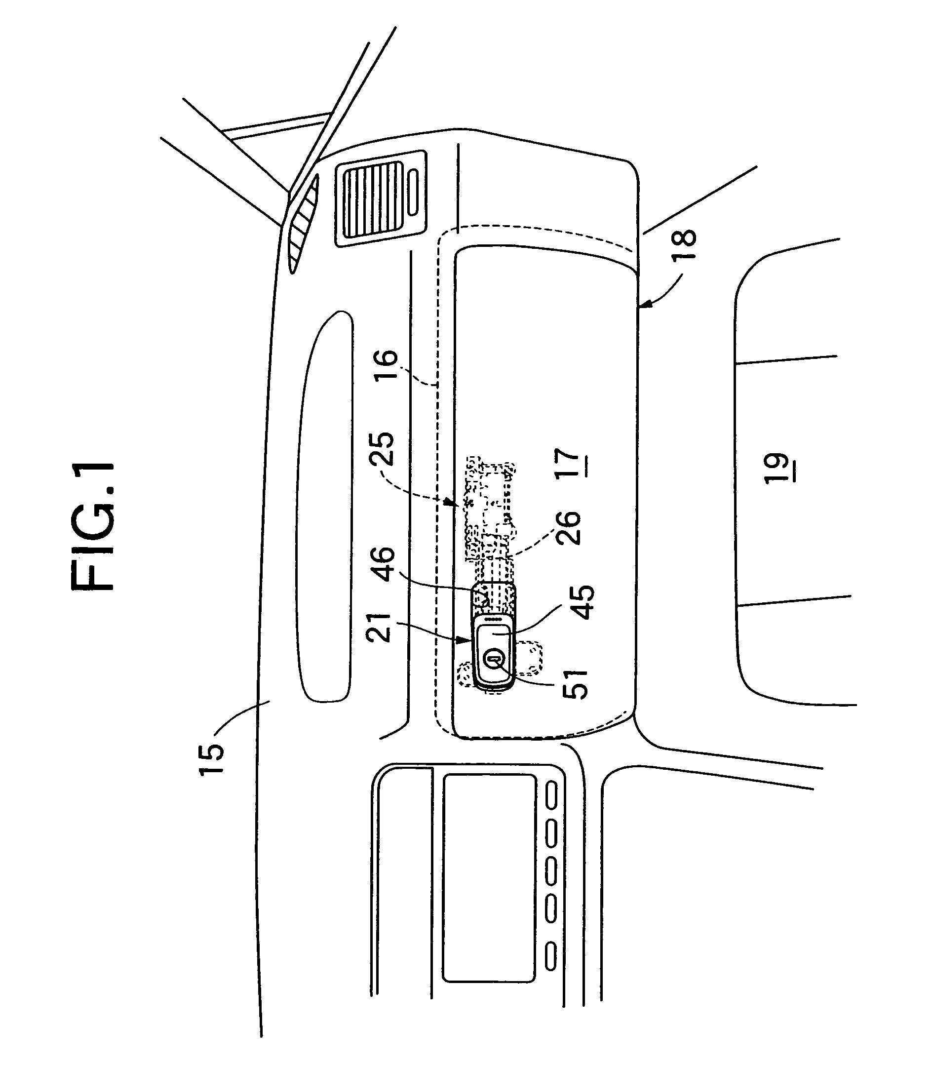
[0024]Referring first to FIG. 1, a glove box 18 is mounted on an instrument panel 15 disposed in a front portion in a vehicle compartment of a passenger vehicle, for example, with a left-hand steering wheel, at position in front of an assistant driver's seat. The glove box 18 includes a box body 16 integral with the instrument panel 15, and a lid 17 capable of opening and closing an opening in the box body 16 by its vertical turning about a horizontal axis.

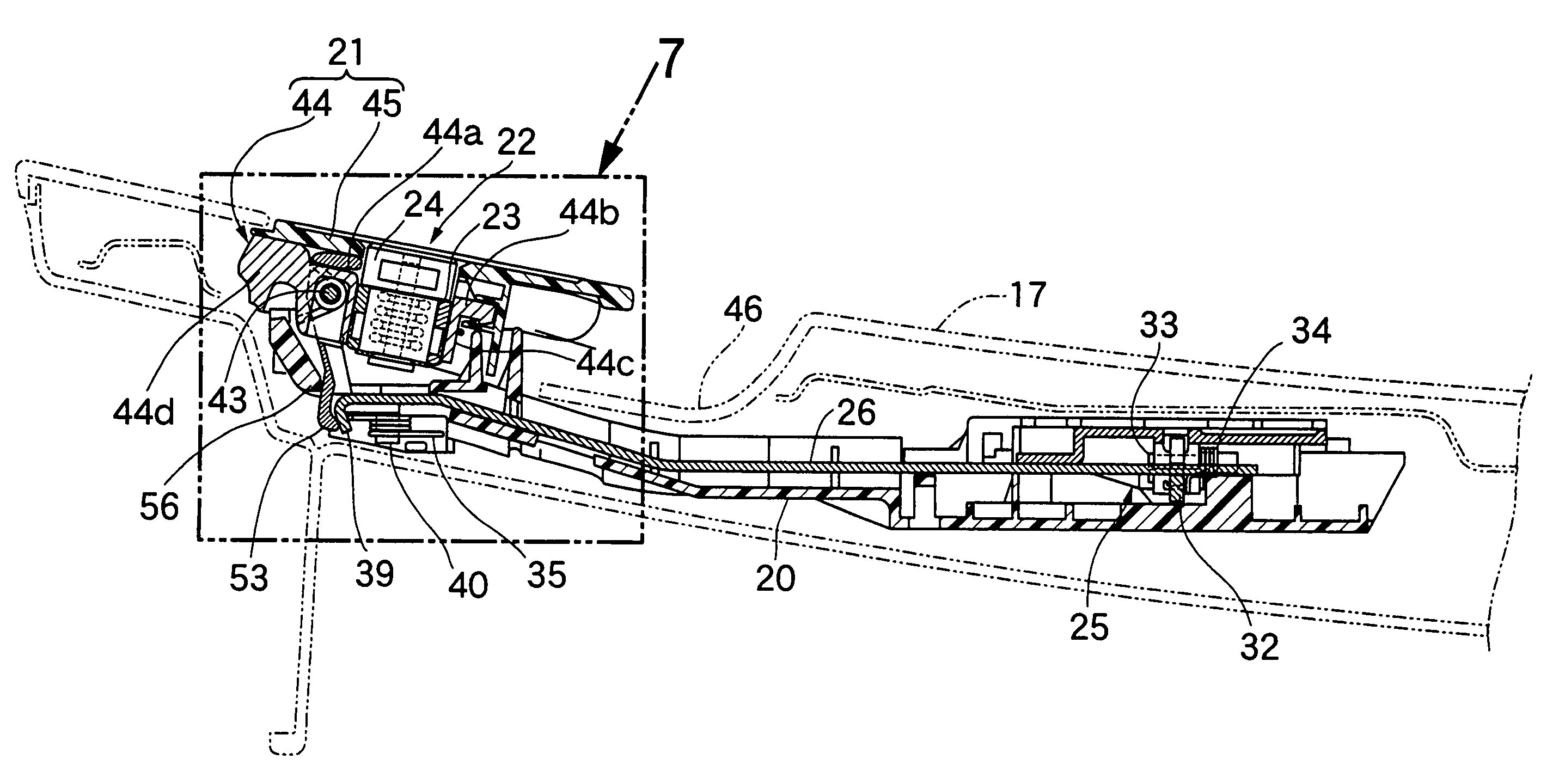
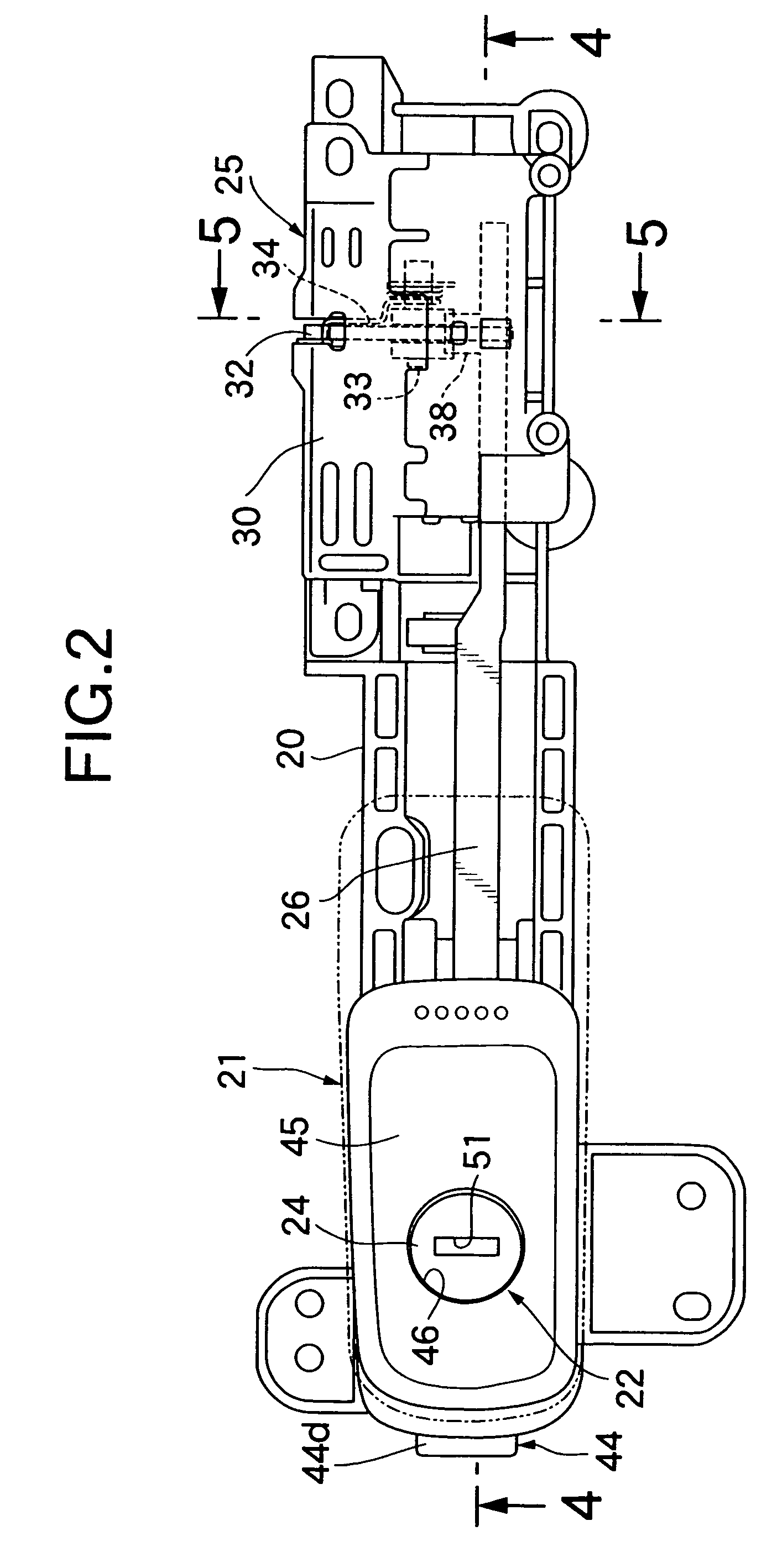
[0025]Referring to FIGS. 2 to 4 together, a base member 20 made of a synthetic resin is attached to and accommodated within the lid 17 made of a synthetic resin, so that the base member 20 extends in the left / right direction. A steering handle 21 is turnably carried at one end in the left / right direction (at a left end in this embodiment) of the base member 20. A cylinder lock 22 comprises a cylinder 23 fixed to the operating handle 21, and a rotor 24 turnably inserted into the cylinder 23 so that the rotor 24 can turn between a l...


PUM


Abstract

In a glove box device, a cylinder is fixed to an operating handle, a slide member switches between a locking state and an unlocking state in correspondence to sliding motion, and a connecting member is interposed between one end of the slide member and a rotor. The connecting member transmits a turning force of the rotor turning along with the operating handle to the slide member, to move the slide member from a locking position to an unlocking position when the rotor is in the unlocking position. The connecting member cuts off the transmission of turning force between the slide member in the locking position and the rotor, when the rotor is in the locking position. Thus, it is possible to reduce the number of components needed, and also to reduce a gap between a design face of the operating handle and the cylinder lock, thereby improving the appearance.

Description

CROSS-REFERENCE TO RELATED APPLICATION[0001]The present invention claims priority under 35 USC 119 based on Japanese patent application No. 2005-338904, filed on Nov. 24, 2005. The subject matter of this priority document is incorporated by reference herein.BACKGROUND OF THE INVENTION[0002]1. Field of the Invention[0003]The present invention relates to a glove box device, and particularly to an improvement of a glove box device including a cylinder lock for switching over a locked state and an unlocked state of a lid.[0004]2. Description of the Related Art[0005]Japanese Patent Application Laid-open No. 2004-76449 discloses a glove box device wherein an operating handle capable of turning in a horizontal direction is supported on a base member mounted to a lid covering an opening of a box body, and a transmission mechanism is operated by locking and unlocking operations of a cylinder lock mounted on a stationary portion separate from the operating handle, whereby transmission and cut...

Claims


Application Information

Patent Timeline
Patent Type & Authority Patents(United States)
IPC IPC(8): B60R25/02B60R7/06E05B83/30
CPCB60R7/06E05B83/30E05B5/00Y10S292/30Y10T292/1047Y10T70/5761
Inventor YUKIHARA, JINMIYAGAWA, TAKUYA
Owner HONDA LOCK MFG CO LTD
Why Eureka
Try Eureka