Eureka AIR delivers breakthrough ideas for toughest innovation challenges, trusted by R&D personnel around the world.

Dual axis grinder blender

Inactive Publication Date: 2009-10-20
LANG WILLIAM J
View PDF26 Cites 45 Cited by
  • Summary
  • Abstract
  • Description
  • Claims
  • Application Information

AI Technical Summary

Benefits of technology

[0018]Auger flighting on the auger tube improves blending when working in loose material with excess liquid. An auger tube without auger flighting is preferred when working in hard compact soils in dry conditions.

Problems solved by technology

If the soil agitated is contaminated, the chemical added may convert the contaminant into a non-hazardous material, destroy the contaminant, or contain the contaminant.
Soil that is contaminated by a percolation of a contaminate into the soil may be hard and dense due to the fact that it has not been moved by man, by natural erosion or by earthquakes for several centuries.

Method used


Image

  • Dual axis grinder blender
  • Dual axis grinder blender
  • Dual axis grinder blender

Examples


Embodiment Construction

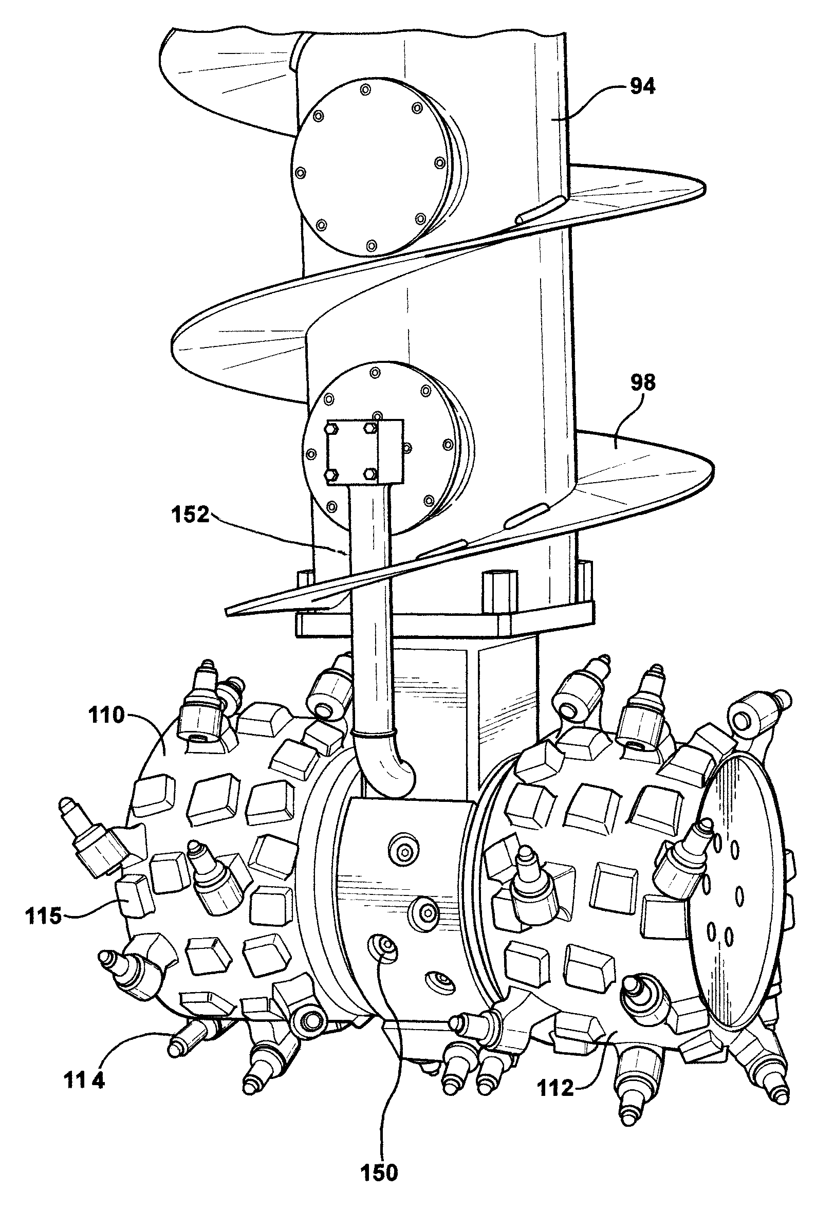
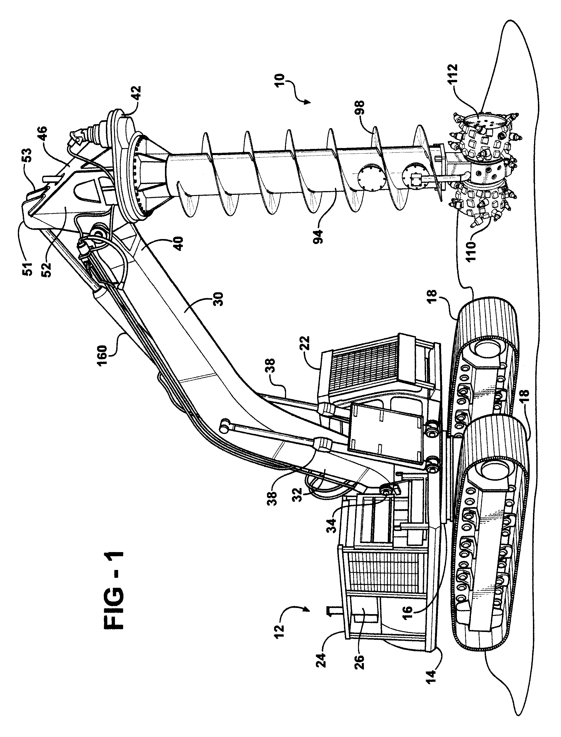
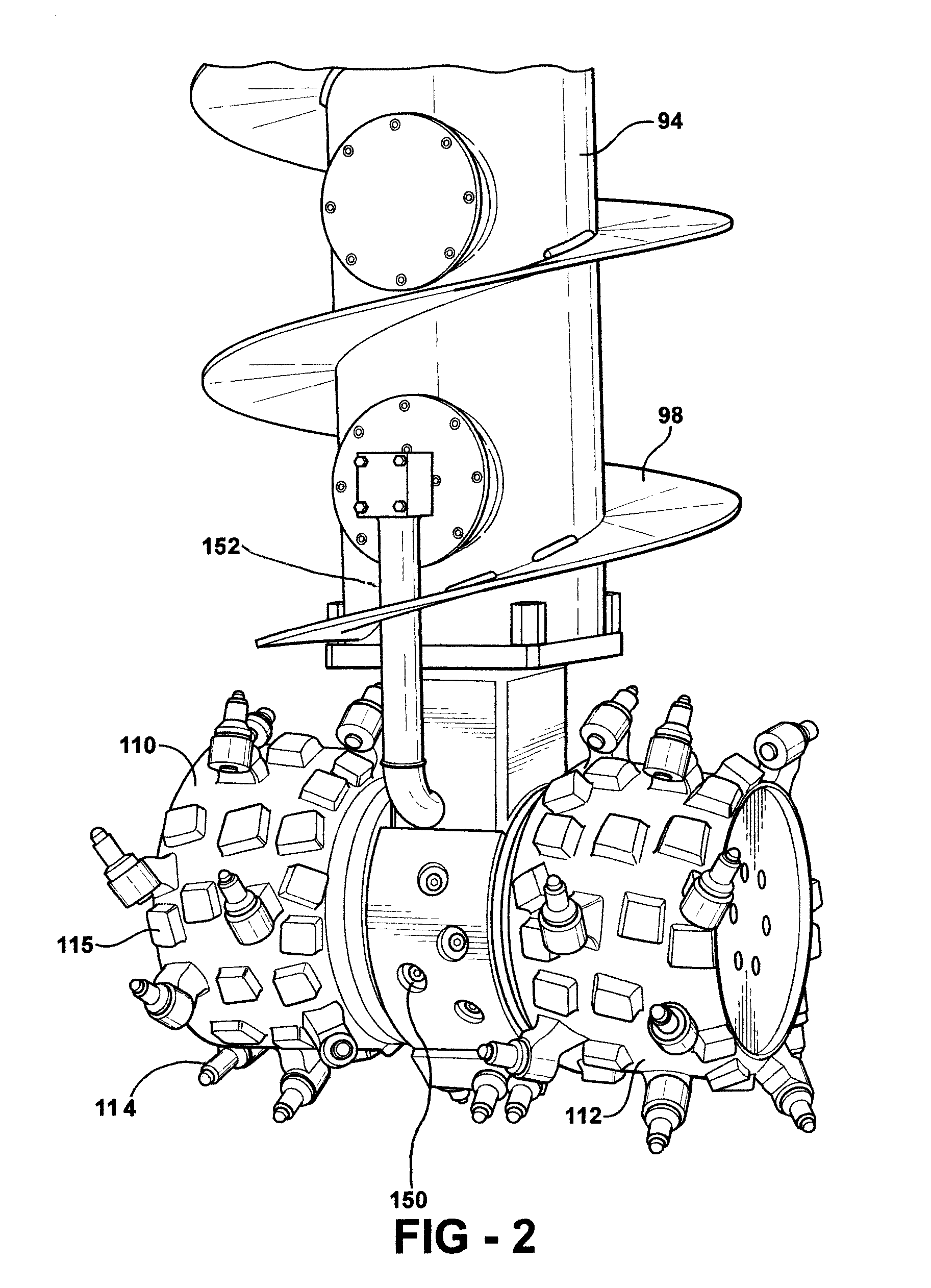
[0027]The dual axis grinder blender assembly 10 is an attachment to a hydraulic excavator 12. The hydraulic excavator includes an excavator frame 14 pivotally attached to a tracked carriage 16 with two space apart parallel track assemblies 18. The excavator frame 14 pivots about a center vertical pivot axis 20.

[0028]An operator's enclosure 22 is mounted on a forward portion of the excavator frame 14. An engine enclosure 24 is mounted on the excavator frame 14 to the rear of the operator's enclosure 22. An engine 26 mounted in the engine enclosure 24 drives one or more hydraulic pumps 28. The pumps 28 supply hydraulic fluid under pressure to operate the excavator 12 and the dual axis blender 10.

[0029]An excavator boom 30 has a boom excavator end 32 pivotally attached to the frame 14, by a boom pivot assembly 34, for pivotal movement about a transverse horizontal boom axis 36. One or more hydraulic cylinders 38 pivot the excavator boom 30 about the boom axis 36 to raise and lower the ...


PUM


Abstract

The dual axis grinder includes a support frame with a plate and a mast. The mast is connected to the boom of an excavator and to a hydraulic stick control cylinder. An auger tube is journaled in a bore through the support frame plate for rotation about a vertical axis. Auger flighting may be attached to the auger tube. A central support housing is attached to the bottom of the auger tube. Two cylindrical drums with grinder teeth are journaled on the central support housing for rotation about a horizontal axis that intersects the vertical axis. The auger tube is rotated by a reversible hydraulic motor. The cylindrical drums are driven by one or two reversible hydraulic motors. Hydraulic fluid is provided to drive the two drums cylindrical through a rotary hydraulic manifold. Chemicals to treat environmental contaminates are supplied through a nozzle adjacent to the cylindrical drums.

Description

CROSS REFERENCE TO RELATED APPLICATIONS[0001]This application claims the benefit of the filing date of U.S. Provisional Application No. 60 / 873,491 titled DUAL AXIS BLENDER, filed Dec. 7, 2006.TECHNICAL FIELD[0002]The dual axis grinder blender includes a driven horizontal axis grinder mixer mounted on a lower end of a driven vertical tube, with auger flighting that rotates about a vertical axis to lift soil and contaminates upward.BACKGROUND OF THE INVENTION[0003]Contamination of the environment has many potential sources. Environmental clean up is required to contain environmental contamination and thereby prevent further damage to the environment. Contamination of soil occurs when contaminants are spilled or dumped on the ground and percolate into the soil. Materials such as hydrocarbons, degreasers, pesticides, dry cleaning fluids, paint solvents, fertilizers and industrial chemicals frequently percolate into the soil. Clean up of such contaminates is generally difficult. Some mat...

Claims


Application Information

Patent Timeline
IPC IPC(8): E02F3/96
CPCE02D3/126E02F3/246E02F3/24E02F3/205
Inventor LANG, WILLIAM J.
Owner LANG WILLIAM J
Why Eureka
Eureka Blog
Learn More