Optical deflector
a technology of optical deflector and optical frame, which is applied in the field of optical deflector, can solve the problems of affecting the operation of the optical deflector, the overall size of the module becomes large, and the loss of the advantages of the mems device, such as being small in size and having high functionality, and achieves stable deflection and scanning performance. , the effect of reducing the abnormal vibration of the mirror and reducing the abnormal vibration of the movable fram
- Summary
- Abstract
- Description
- Claims
- Application Information
AI Technical Summary
Benefits of technology
Problems solved by technology
Method used
Image
Examples
first embodiment
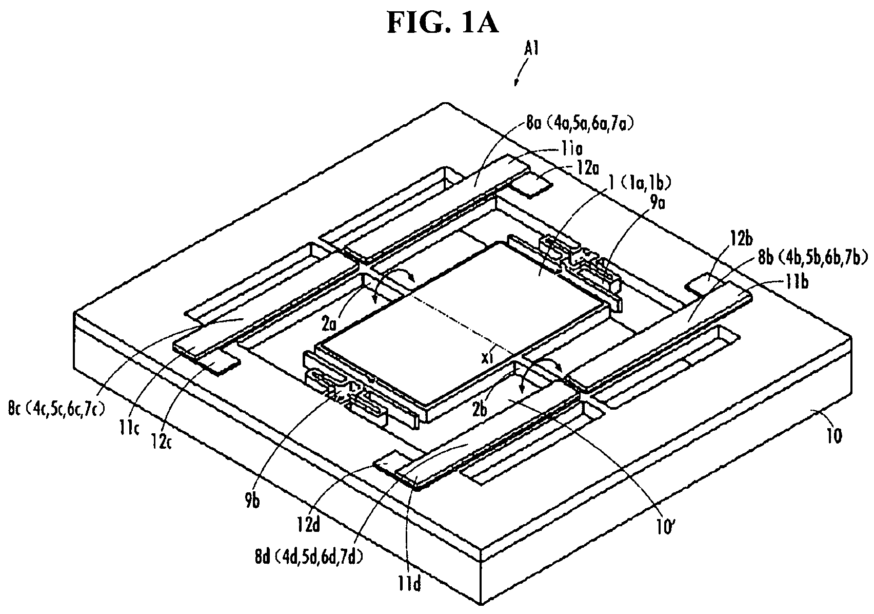
[0050]With reference to FIGS. 1A to 2H, an optical deflector according to a first embodiment of the present invention is described. FIG. 1A is a perspective view of the optical deflector A1 according to the present embodiment. FIGS. 2A-2H2 illustrate a manufacturing process of the optical deflector A1 of FIG. 1A.
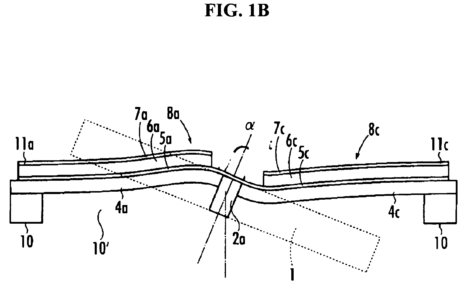
[0051]As shown in FIG. 1A, the optical deflector A1 of the present embodiment includes a mirror 1 which reflects incoming light, torsion bars 2a, 2b which are connected to the mirror 1, piezoelectric actuators 8a-8d which rotarily drive the mirror 1 through the torsion bars 2a, 2b, a support 10 which supports the piezoelectric actuators 8a-8d, and impact attenuators 9a, 9b which are connected to the support 10.
[0052]The mirror 1 is rectangular in its shape, and a pair of torsion bars 2a, 2b extend outwardly from the center of respective sides of the mirror 1. The anchoring end of the torsion bar 2a is connected to the support 10 and the leading end is connected to the mirror...
second embodiment
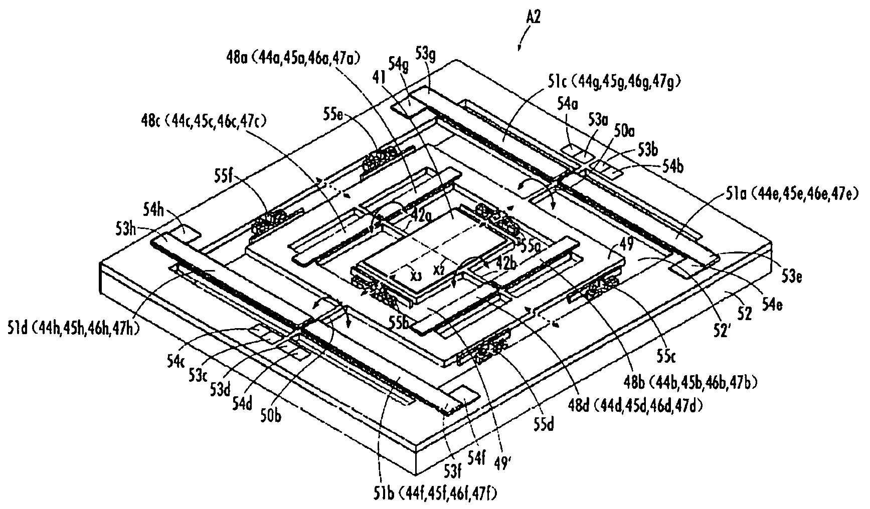
[0100]A second embodiment of the present invention is described with reference to FIG. 3. FIG. 3 is a perspective view showing a configuration of optical deflector A2 of the second embodiment of the present invention. The optical deflector A2 of the present embodiment is equipped with additional two pairs of piezoelectric actuators in order to rotarily drive, as a unit, the mirror, the torsion bars, and two pairs of the piezoelectric actuators of the first embodiment.
[0101]The optical deflector A2 of the present embodiment includes a mirror 41 which reflects incident light, first torsion bars 42a, 42b connected to the mirror 41, two pairs of inner first piezoelectric actuators 48a-48d, movable frame 49 supporting the first piezoelectric actuators 48a-48d, second torsion bars 50a, 50b connected to the movable frame 49, two pairs of outer second piezoelectric actuators 51a-51d, and support 52 which supports the second piezoelectric actuators 51a-51d.
[0102]The mirror 41 is rectangular...
third embodiment
[0122]A third embodiment of the present invention is explained with reference to FIG. 4. FIG. 4 is a perspective view which shows a configuration of optical deflector A3 according to the third embodiment. The optical deflector A3 of the present embodiment is similar to the first embodiment except that the impact attenuators are different from those provided in the first embodiment. The same reference numerals are used to indicate the same or like elements as in the first embodiment, and explanations of the same or like elements that have been explained above are not repeated below.
[0123]As in the case of the impact attenuators 9a, 9b of the first embodiment, as shown in FIG. 4, impact attenuators 61a, 61b of the present embodiment are installed in a gap 10′ so as to be connected to the support 10 and to face the two opposing sides of the mirror 1 that are perpendicular to the other two opposing sides of the mirror 1 form which the torsion bars 2a, 2b extend outwardly. However, in th...
PUM
 Abstract
Description
Claims
Application Information
 - R&D
- Intellectual Property
- Life Sciences
- Materials
- Tech Scout
- Unparalleled Data Quality
- Higher Quality Content
- 60% Fewer Hallucinations
Browse by: Latest US Patents, China's latest patents, Technical Efficacy Thesaurus, Application Domain, Technology Topic, Popular Technical Reports.
© 2025 PatSnap. All rights reserved.Legal|Privacy policy|Modern Slavery Act Transparency Statement|Sitemap|About US| Contact US: help@patsnap.com


