
Devices and methods for cardiac mapping of an annular region

a technology of annular region and device, applied in the field of medical devices, can solve problems such as side effects, atrial flutter, rapid heart contraction,

Active Publication Date: 2009-10-20
IRVINE BIOMEDICAL
View PDF13 Cites 57 Cited by
  • Summary
  • Abstract
  • Description
  • Claims
  • Application Information

AI Technical Summary

Benefits of technology

"The present invention provides a catheter and method for mapping and pacing in the tricuspid valve region. The catheter has a soft distal tip section that moves and rebounds longitudinally, allowing for easier mapping and pacing of the heart. The catheter has a pre-shaped curved distal section with a plurality of electrodes for mapping and pacing. The catheter can be easily adjusted for different heart conditions and can be deflected for more precise mapping and pacing."

Problems solved by technology

The presence of an arrhythmogenic region or an accessory pathway in the atria can bypass or short circuit the normal pathway, potentially resulting in very rapid heart contractions, referred to here as atrial flutter.
While drugs may be the choice of treatment for many patients, they only mask the symptoms and do not cure the underlying causes, and they may also cause side effects.
Implantable devices only correct the arrhythmia after it occurs.
There are, however, several drawbacks of the currently-available mapping catheters when used in locating areas of aberrant electrical conduction for the catheter-based ablation of an annular region of the heart such as the tricuspid valve.
Due to the varying anatomy of this area between different patients, one of the major problems lies in the unstable positioning of the catheter electrodes around the triscuspid valve annulus.
When a catheter is not stabilized, the electrodes cannot maintain sufficient contact with the target tissue and hence the heart's electrical conduction pattern becomes difficult to map and establish.
Furthermore, many of these currently-available catheters lack a soft distal tip portion so that the shock from contacting the catheter tip on the tissue can be absorbed.

Method used


Image

  • Devices and methods for cardiac mapping of an annular region
  • Devices and methods for cardiac mapping of an annular region
  • Devices and methods for cardiac mapping of an annular region

Examples


Embodiment Construction

[0020]The following detailed description is of the best presently contemplated modes of carrying out the invention. This description is not to be taken in a limiting sense, but is made merely for the purpose of illustrating general principles of embodiments of the invention. The scope of the invention is best defined by the appended claims. In certain instances, detailed descriptions of well-known devices and mechanisms are omitted so as to not obscure the description of the present invention with unnecessary detail.

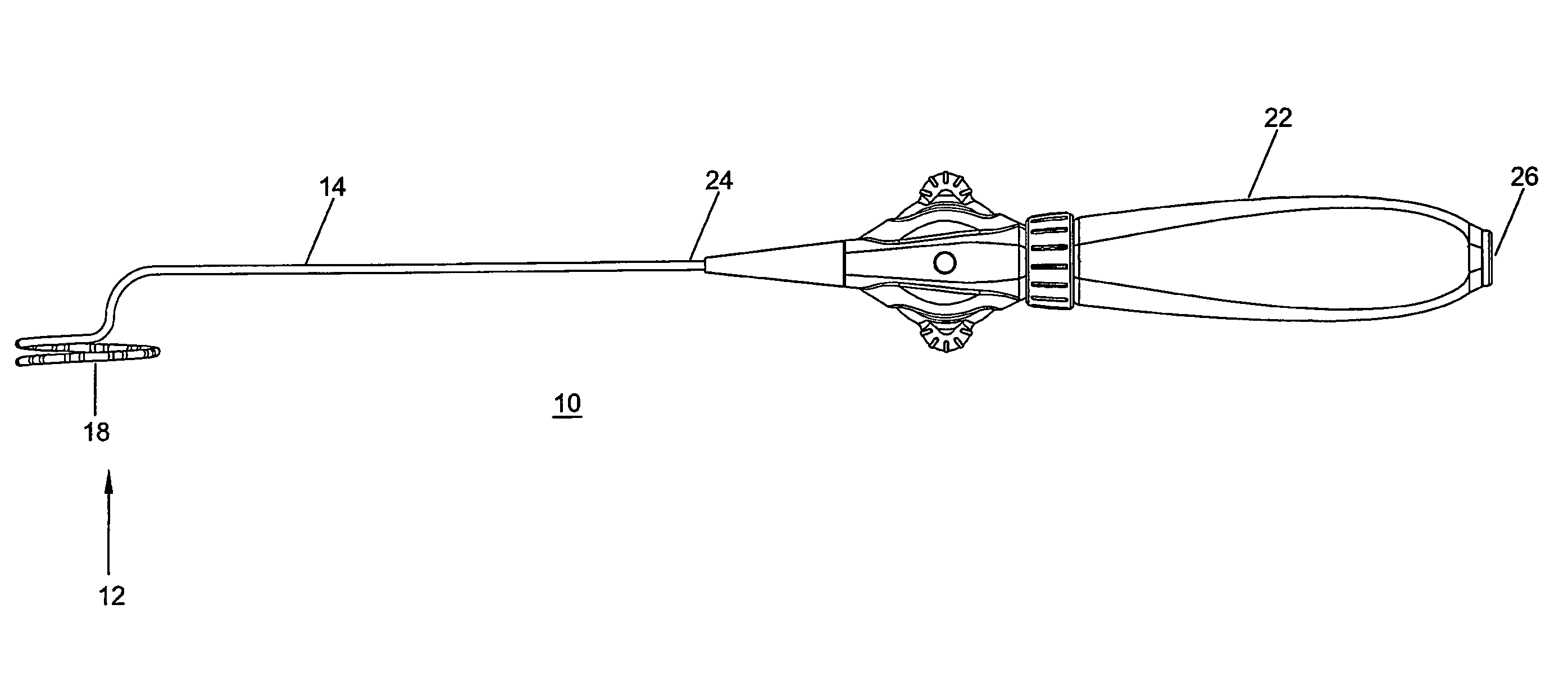
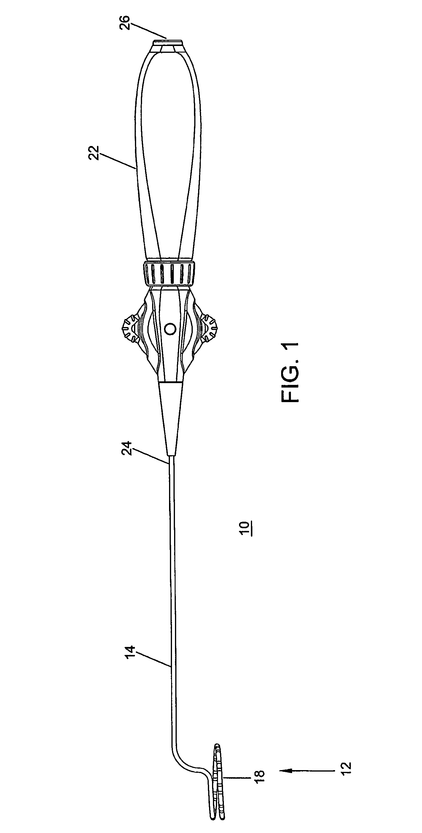
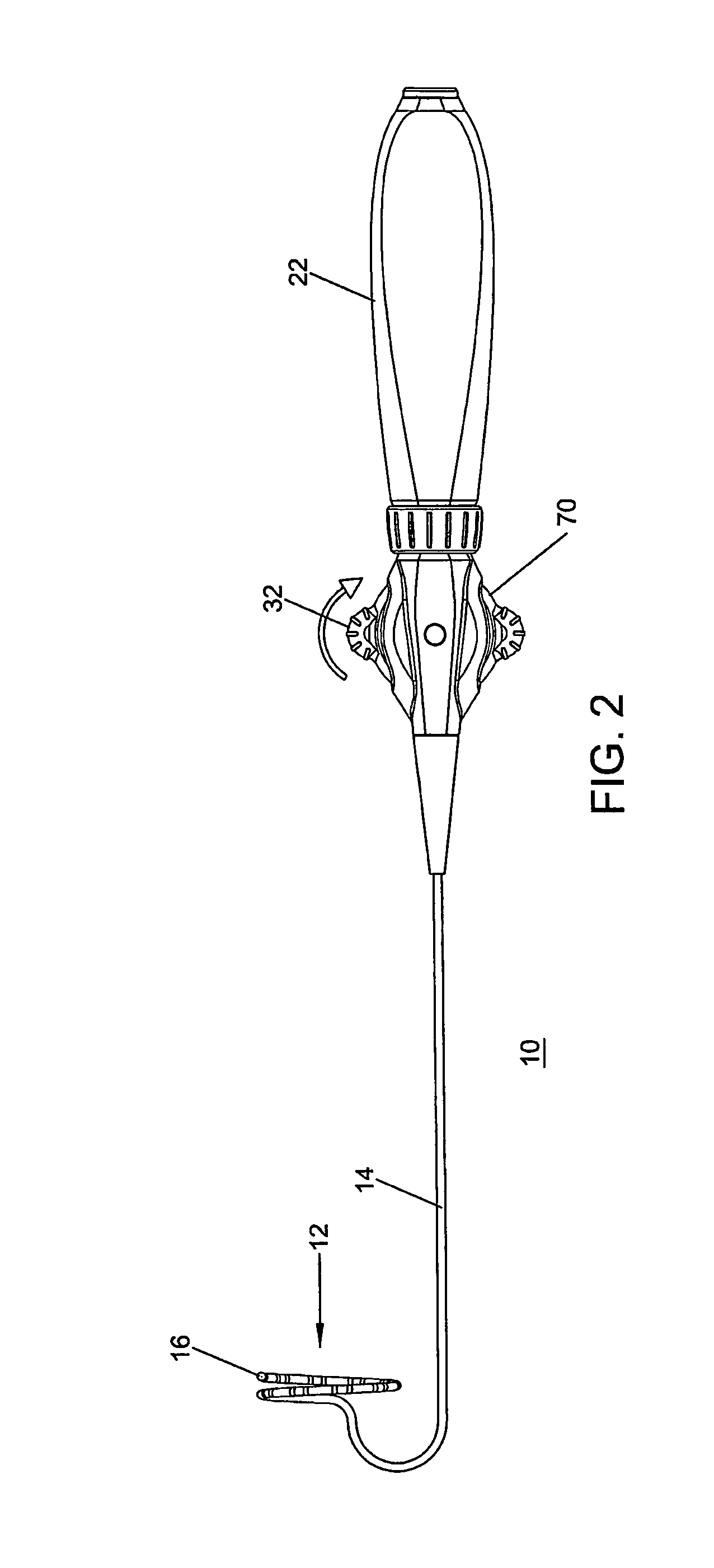
[0021]FIGS. 1-7 illustrate a catheter 10 having a catheter body 14 that comprises an elongated tubular construction having a single, axial or central lumen 20. The catheter body 14 is flexible, i.e., bendable, but substantially non-compressible along its length. The catheter body 14 can be of any suitable construction and made of any suitable material. A presently preferred construction comprises an outer wall made of polyurethane or PEBAX. The outer wall can comprise an...


PUM


Abstract

A catheter maps an electrical conduction pattern in an annular region of a heart. The catheter has a tubular shaft that has a pre-shaped curved distal section adjacent the distal end thereof, and at least one lumen extending between the distal end and the proximal end of the shaft, with a plurality of electrodes disposed on the distal section. A handle is attached to the proximal end of the shaft, with a steering mechanism provided at the handle for adjusting the curvature of the distal section, and a deflection mechanism provided at the handle for deflecting the distal section. The electrodes are positioned in a parallel plane separate from the shaft when the distal section is undeflected.

Description

BACKGROUND OF THE INVENTION[0001]1. Field of the Invention[0002]The present invention generally relates to a medical device and its use for mapping electrical activity inside the heart especially in the tricuspid valve.[0003]2. Description of the Prior Art[0004]Symptoms of abnormal heart rhythms are generally referred to as cardiac arrhythmias, while an abnormally rapid rhythm is referred to as a tachycardia. The present invention is concerned with the diagnosis and treatment of tachycardias, which are frequently caused by the presence of an “arrhythmogenic region” or an “accessory atrioventricular pathway” close to the inner surface of the atrium of a heart. The heart includes a number of normal pathways, which are responsible for the propagation of electrical signals from the upper chamber to the lower chamber, and which are necessary for performing normal systole and diastole function. The presence of an arrhythmogenic region or an accessory pathway in the atria can bypass or sho...

Claims


Application Information

Patent Timeline
Patent Type & Authority Patents(United States)
IPC IPC(8): A61B5/042
CPCA61B5/6852A61B5/0422A61B5/287
Inventor MURANUSHI, MASAMITSUHIGASHIKUBO, TAKASHIROY, PIANKA
Owner IRVINE BIOMEDICAL
Learn More