Jackhammer lift assist

a technology of lift assist and jackhammer, which is applied in the direction of percussive tools, manufacturing tools, portable drilling machines, etc., can solve the problems of preventing the operator from being able to operate the hammer for an extended period of time, heavy percussion power tools, and a great physical stress on the operator, so as to reduce the physical demands of its operation and simplify the operation.

Active Publication Date: 2009-10-27
INTEGRATED TOOL SOLUTIONS
View PDF10 Cites 8 Cited by
  • Summary
  • Abstract
  • Description
  • Claims
  • Application Information

AI Technical Summary

Benefits of technology

[0010]In accordance with the present invention, a lift assist device is provided for use with a conventional percussion power tool, such as a pneumatic jackhammer, to reduce the physical demands for its operation by facilitating the lifting and the extracting of the equipment. In general, the lift assist device contains an actuating cylinder with a lifting foot attached to the outside end of its piston rod and a control unit which comprises a directional control valve and a hand lever. The control unit is on the top of the lift assist device whereas the lifting foot is on the bottom to engage with the working surface. The directional control valve is operated using the hand lever, preferably adjacent to one of the handles of the percussion power tool to simplify its operation. The lift assist device is secured to the body of the percussion power tool with two mounting elements, preferably one close to the top of the lift assist device and the upper body of the percussion power tool and the other close to the bottom of the lift assist device and the lower body of the percussion power tool.

Problems solved by technology

As such, the percussion power tool tends to be very heavy, typically having a weight of from about 60 to 100 pounds.
When working with a tool of such weights, the operator has to endure a great physical stress and is thus prevented from being able to operate the hammer for an extended period of time.
Furthermore, the chisel bit is also often jammed into the material being worked and requires a great deal of effort to remove, which makes the operation even more physically demanding.
As a consequence, it greatly reduces the productivity but also poses a great health risk to its operators.
One significant limitation of this prototype is that the lift assist device is heavy with an overall weight of over 20 pounds, which adds additional unnecessary physical burdens to the operator.
However, these previous lift assist devices have some disadvantages.

Method used


Image

  • Jackhammer lift assist
  • Jackhammer lift assist
  • Jackhammer lift assist

Examples


Embodiment Construction

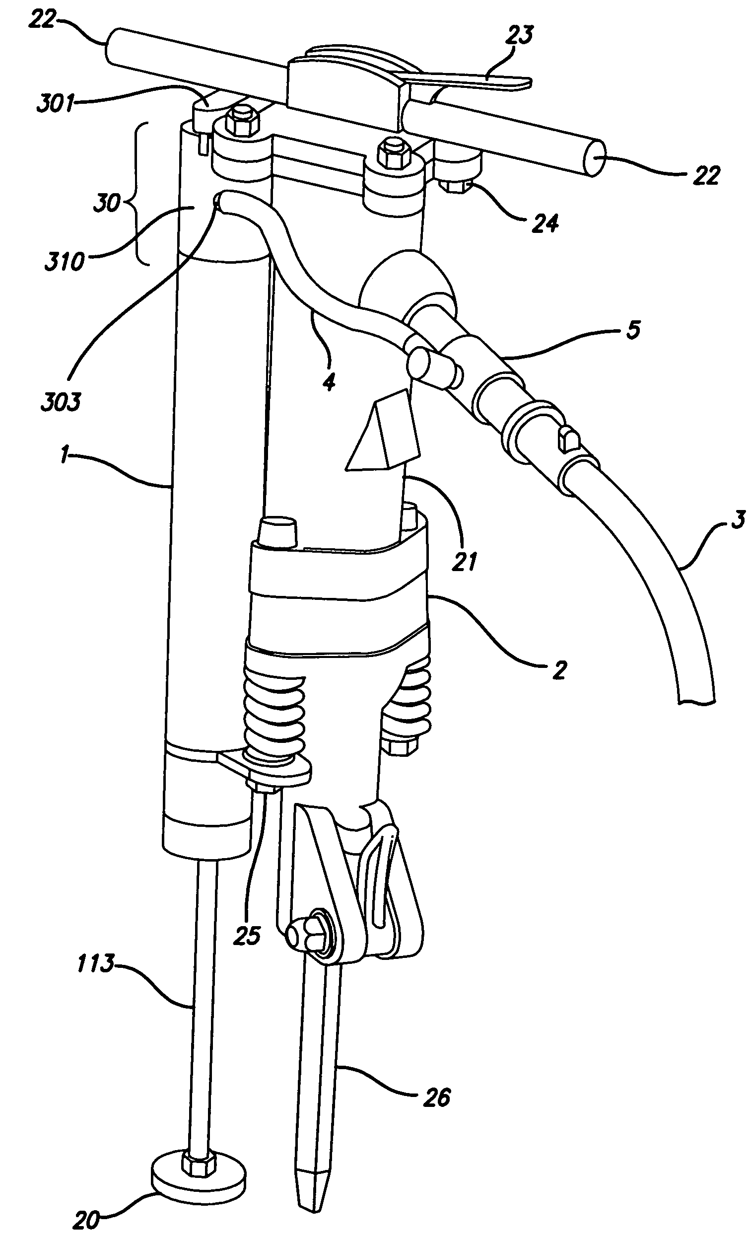
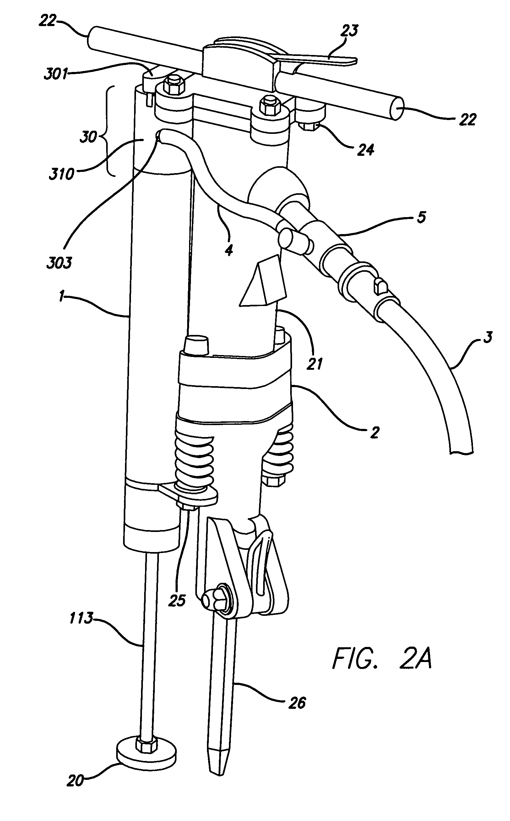
[0031]The present invention relates to a lift assist device 1 which is used to alleviate the physical demands for the operation of a heavy percussion power tool 2 by facilitating the lifting and the extracting of the percussion power tool 2 (FIG. 2A). The lift assist device 1 can be used with a variety of percussion power tools, such as a jackhammer and rock drill. A percussion power tool 2 is commonly powered by compressed air. It can also be powered by hydraulic or electrical powers. A percussion power tool 2 is normally used for breaking up rock, concrete, road pavement such as asphalt and macadam, and earth. Commercial percussion power tools are supplied in a variety of weights and heights to suit particular applications. For example, American Pneumatic Tools, Inc. (Gardena, Calif.) provides several series of pneumatic tools, including Airgo-line paving breakers (e.g., Model 140A, 160A, and 190A), paving breakers (e.g., Model 117, 140 160, and 190), rock drills (e.g., Model 109,...


PUM

PropertyMeasurementUnit
weightaaaaaaaaaa
weightaaaaaaaaaa
pressureaaaaaaaaaa

Abstract

The present invention relates to a lift assist device which is used to alleviate the physical demands for the operation of a heavy percussion power tool, such as a pneumatic jackhammer, by facilitating lifting and freeing the percussion power tool. In general, the lift assist device contains an actuating cylinder with a lifting foot attached to the outside end of its piston rod and a control unit which comprises a directional control valve and a hand lever. The control unit is on the top of the lift assist device and can be used to control the lifting speed and height. The lift assist device is secured to the body of the percussion power tool with one or more mounting elements.

Description

TECHNICAL FIELD[0001]The present invention relates to a lift assist device which is used to alleviate the physical demands for the operation of a heavy percussion power tool by facilitating lifting and freeing the percussion power tool from the working surface.BACKGROUND OF THE INVENTION[0002]A portable percussion power tool such as a pneumatic jackhammer employs a linearly reciprocating piston-driven anvil which rapidly and repeatedly hammers on the end of the chisel bit and impels it into a working surface. Its effectiveness relies on the inertia of the mass of its body and gravity is also required to bring the mass back into contact with the working surface after each blow. As such, the percussion power tool tends to be very heavy, typically having a weight of from about 60 to 100 pounds. During a routine operation, an operator is required to repetitively lift and reposition the heavy device for next operation. When working with a tool of such weights, the operator has to endure ...

Claims


Application Information

Patent Timeline
Patent Type & Authority Patents(United States)
IPC IPC(8): B27C3/08
CPCB25D17/30B23B2270/027
Inventor SORRIC, RONALD JONSORRIC, RONALD WILLIAM
Owner INTEGRATED TOOL SOLUTIONS
Why Eureka
Try Eureka