Insert with ventilation

a technology of inserting and ventilation, applied in the field of inserting, can solve the problems of unable to access the fan unit from below the ceiling, unable to maintain the unit, and unable to generate heat from halogen light sources

Inactive Publication Date: 2009-10-27
DAXTOR
View PDF15 Cites 58 Cited by
  • Summary
  • Abstract
  • Description
  • Claims
  • Application Information

AI Technical Summary

Benefits of technology

[0033]The lowering of the temperature has a number of advantageous effects. First of all, the life expectancy of the light source may be increased and at the same time the fire hazard immediately adjacent the installation is reduced dramatically. Furthermore, by arranging the fan such that the air current is directed into the room where the light is emitted, the heat produced by the light source and the fan is ventilated into the room and may therefore be used for heating purposes. Furthermore, as warm air is lighter than cold air, the warm air produced in order to provide a comfortable temperature in the living zone may be lowered in that the light source, due to the fans, will create a circulation of the air immediately adjacent the ceiling such that the warm air gathering along the ceiling will be forced downwards due to the air streams created by the cooling fans.
[0034]In a still further advantageous embodiment of the invention the insert is provided with means for attaching the electrical installation means, and that further means are provided for allowing the air stream created by the ventilation means to pass the electrical installation means.
[0035]The invention will now be explained in detail with respect to the accompanying drawing, wherein

Problems solved by technology

An additional problem concerning built-in spotlights in particular is generation of heat from halogen light sources which are predominant in the interior design, especially of stores and shops.
The installation requires a number of parts, and furthermore once the connection box and the electrical connections are arranged it is impossible to access the fan unit from below the ceiling.
Thereby cleaning and maintenance of the unit is severely hampered as a complete demounting of the unit is required in order to gain access to the unit.

Method used


Image

  • Insert with ventilation
  • Insert with ventilation
  • Insert with ventilation

Examples


Embodiment Construction

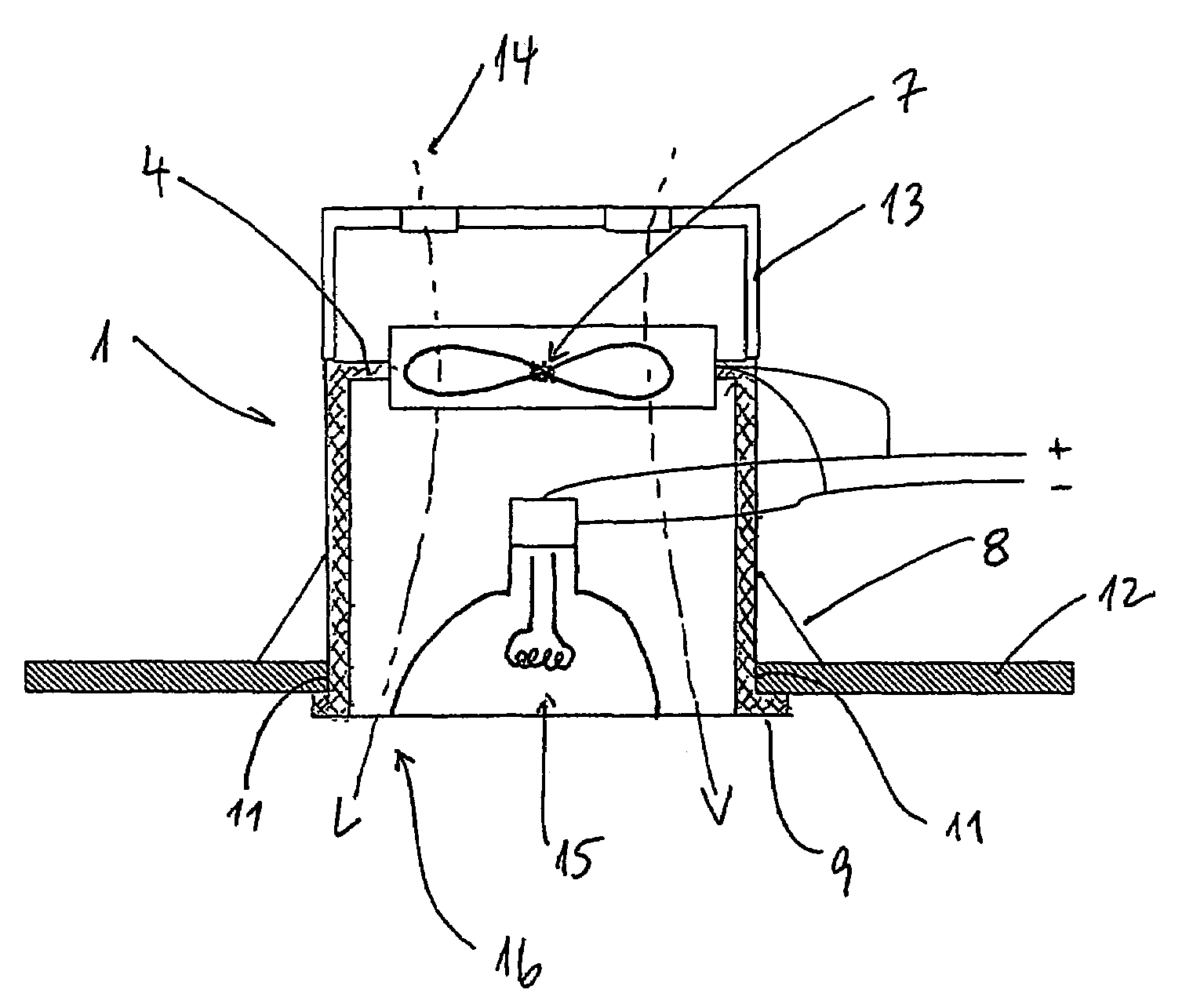
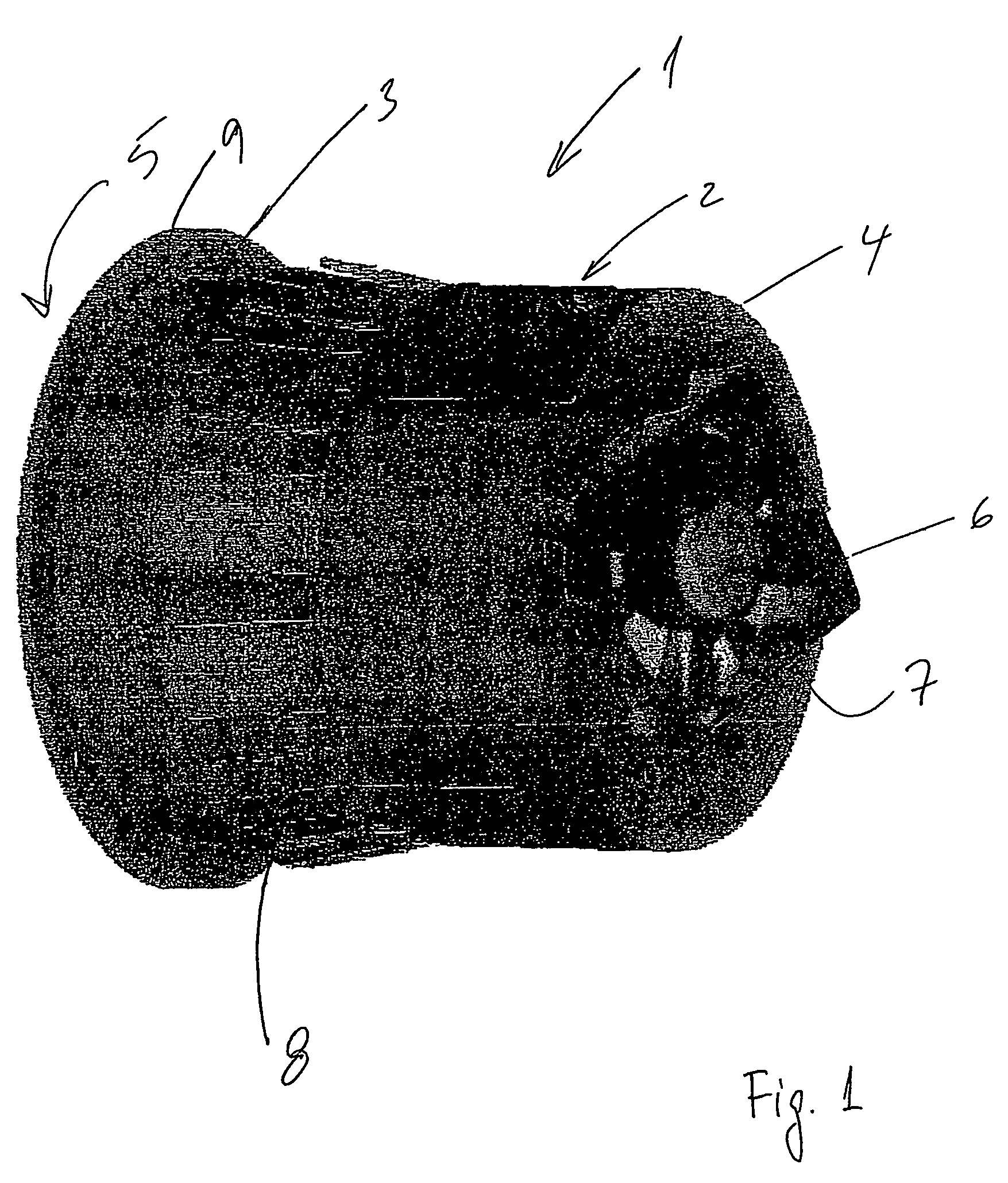
[0044]An insert according to the invention is illustrated in FIG. 1. The insert 1 is in this embodiment an expansion unit made up of two coaxially arranged elements 2,3. The end 4 of the insert is opposite an aperture 5 allowing access to the inside of the insert 1. In the end 4 a ventilating means 6 is arranged. In this embodiment the ventilating means comprises a fan having a number of wings 7.

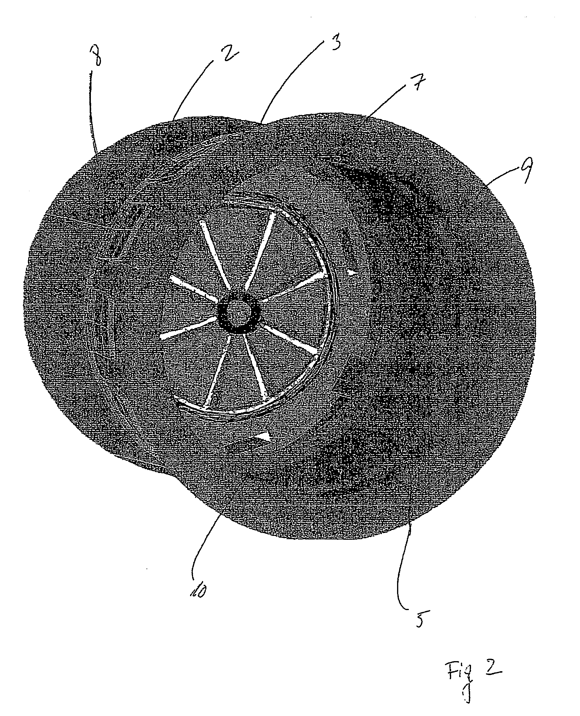
[0045]In FIG. 2 the insert is illustrated from below such that a view is allowed through the aperture into the interior of the insert. The reference numbers correspond to reference numbers from FIG. 1.

[0046]By using the expansion unit as insert, the insert may be installed in a very simple manner in that first an aperture is made in the ceiling, whereafter the unit is inserted through the aperture. A special tool (illustrated in FIG. 4) is inserted in appropriate fastening means in the cylindrical element 2. By pulling the cylindrical element 2 by means of the special tool toward the cylindr...


PUM


Abstract

It is an object of the present invention to provide an insert (1) suitable for being placed in a wall, ceiling or other element wherein an electrical installation means such as a lamp socket or the like may be fitted. Ventilation means (6) are provided inside the insert (1) such that an air current may be created and further that the air current may be led past the electrical installation (15), such that the overall heat accumulation inside the device may be drastically reduced.

Description

[0001]This application claims the benefit of Danish Application No. PA 2003 01863 filed Dec. 16, 2003 and PCT / DK2004 / 000567 filed Aug. 26, 2004, which are hereby incorporated by reference in their entirety.BACKGROUND OF THE INVENTION[0002]The present invention relates to an insert suitable for being placed in a wall, ceiling or other element.[0003]When mounting electrical equipment in wall, ceilings or other elements such as for example kitchen cupboards, book cases, shelves and the like, it is customary to arrange a box inside a cavity made in said element. The electrical wiring is usually led via appropriate piping systems to the connection boxes whereafter electrical equipment such as lamps, switches etc. are arranged, for example as a cover for the electrical connection box. Especially for lamps, the socket is usually arranged in a wire extending through an aperture in the lid of the electrical connection box, such that there is a physical distance between the electrical connect...

Claims


Application Information

Patent Timeline
Patent Type & Authority Patents(United States)
IPC IPC(8): F21V29/00F21V21/04F21V29/02F21V29/15F21V33/00F24F13/078
CPCF21S8/02F21S8/026F21V21/04F21V29/74F21V33/0088F24F13/078F21V29/15F21V29/02F21V29/67
Inventor DAHL, TORBEN
Owner DAXTOR
Why Eureka
Try Eureka