Thermoelectric power generator with intermediate loop

a technology of power generator and loop, which is applied in the direction of thermoelectric devices, machines/engines, mechanical equipment, etc., can solve the problems of reducing the efficiency of thermoelectric generation systems designed for a particular set of conditions, affecting the efficiency of thermoelectric generation systems, and only producing a small fraction of thermoelectric capacity, etc., to achieve the effect of effectively optimizing the performance of a waste heat recovery system, reducing the cost of operation, and improving the control of cold side temperatures

Inactive Publication Date: 2009-10-27
GENTHERM INC
View PDF7 Cites 66 Cited by
  • Summary
  • Abstract
  • Description
  • Claims
  • Application Information

AI Technical Summary

Benefits of technology

[0009]To effectively maximize the performance of a waste heat recovery system using thermoelectrics, maintaining the highest temperature differential across the thermoelectric generator module (TGM) is generally ideal. One way to do this is to keep the hot-side temperatures as high as possible. Another method is to better control the cold-side temperatures. By using an intermediate heat transfer loop and appropriate control for that loop for the hot side, the cold side, or both, significant improvements to power production and / or efficiency are obtained.
[0011]However, once the system becomes dynamic, as in the case of an automobile driven by an engine, where the range of temperatures and heat flux vary greatly, a thermoelectric generation system designed for a particular set of conditions may only produce a small fraction of its capacity, or even become negative under certain operating conditions. In the present invention, by providing a separate heat transfer loop for the cold side, the hot side or both, and appropriate control for such loop or loops, substantial improvements are obtained making such systems feasible in actual use.
[0013]In one embodiment, the system further comprises thermal storage. The thermal storage may be in the intermediate loop, associated with the main heat source or associated with both the intermediate loop and the main heat source. Advantageously, a heat exchanger between the intermediate heat transfer loop and the main heat source facilitates the movement of thermal power from the main heat source to the intermediate heat transfer loop. Preferably, a heat exchanger bypass is controllable via the controller to cause some or all of the heat from the main heat source to bypass the heat exchanger, depending on the heat from the main heat source and the capacity of the thermoelectrics.
[0015]In one embodiment, the heat source is an engine, having a main coolant system. Preferably, the intermediate heat transfer loop can be thermally connectable to the main coolant system of the engine, such that during engine warm-up, heat transferred from the thermoelectrics to the intermediate heat transfer loop is further transferred to the main cooling system for the engine, thereby decreasing warm-up time for the engine. Further, a heat exchanger is advantageously provided between the intermediate heat transfer loop and the main heat source, with an optional a heat exchanger bypass controllable via the controller, to cause some or all of the heat from the main heat source to bypass the heat exchanger.
[0017]In one embodiment, the heat source is an engine, having a main coolant system. In this embodiment, preferably, the intermediate heat transfer loop can be thermally connectable to the main coolant system of the engine. Thereby, during engine warm-up, heat is transferred transferring from the thermoelectrics to the intermediate heat transfer loop and further to the main coolant system for the engine, thereby decreasing warm-up time for the engine.

Problems solved by technology

Thermoelectric (TE) power generation from waste heat has suffered for many reasons in the past.
However, once the system becomes dynamic, as in the case of an automobile driven by an engine, where the range of temperatures and heat flux vary greatly, a thermoelectric generation system designed for a particular set of conditions may only produce a small fraction of its capacity, or even become negative under certain operating conditions.

Method used


Image

  • Thermoelectric power generator with intermediate loop
  • Thermoelectric power generator with intermediate loop
  • Thermoelectric power generator with intermediate loop

Examples


Embodiment Construction

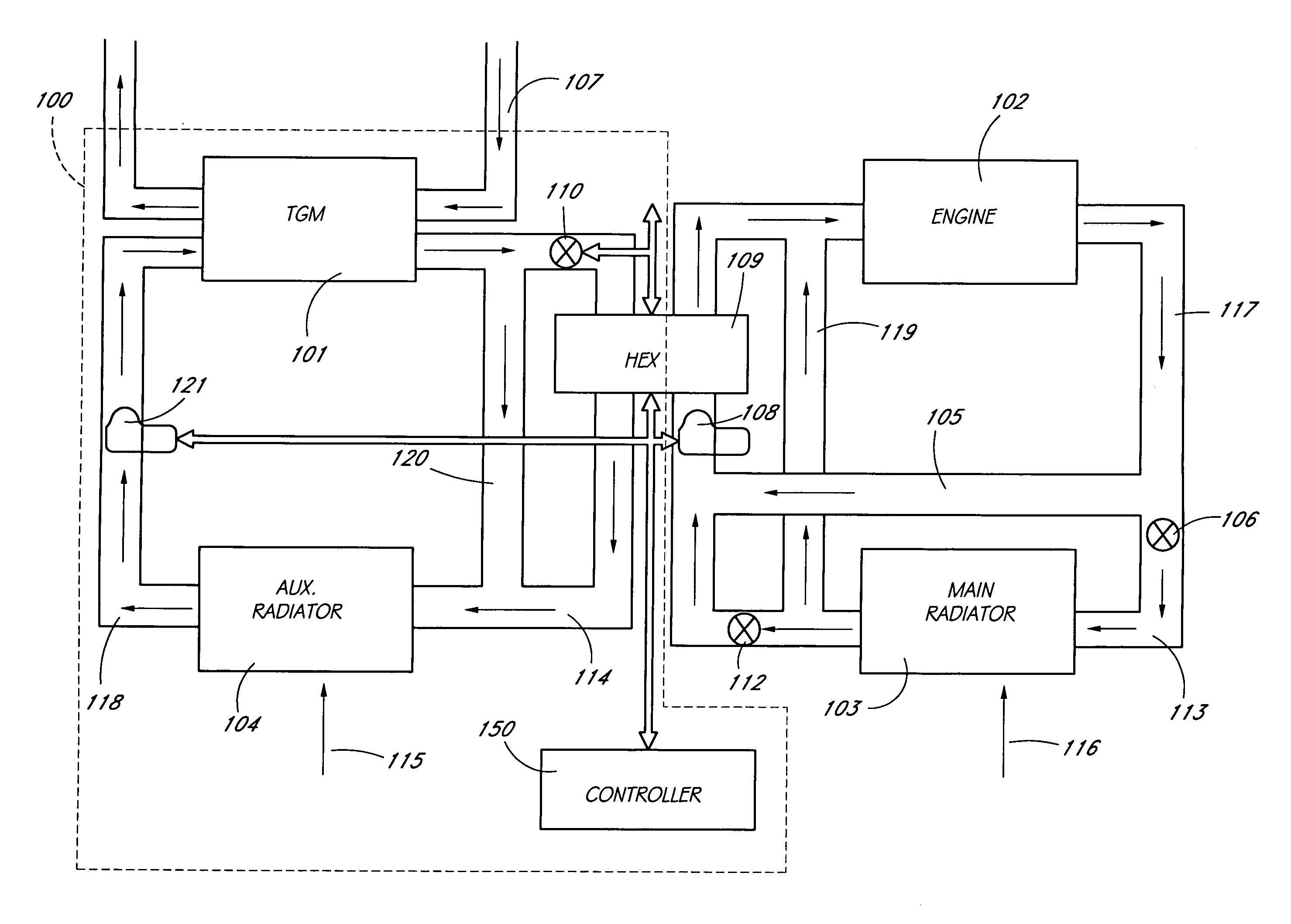
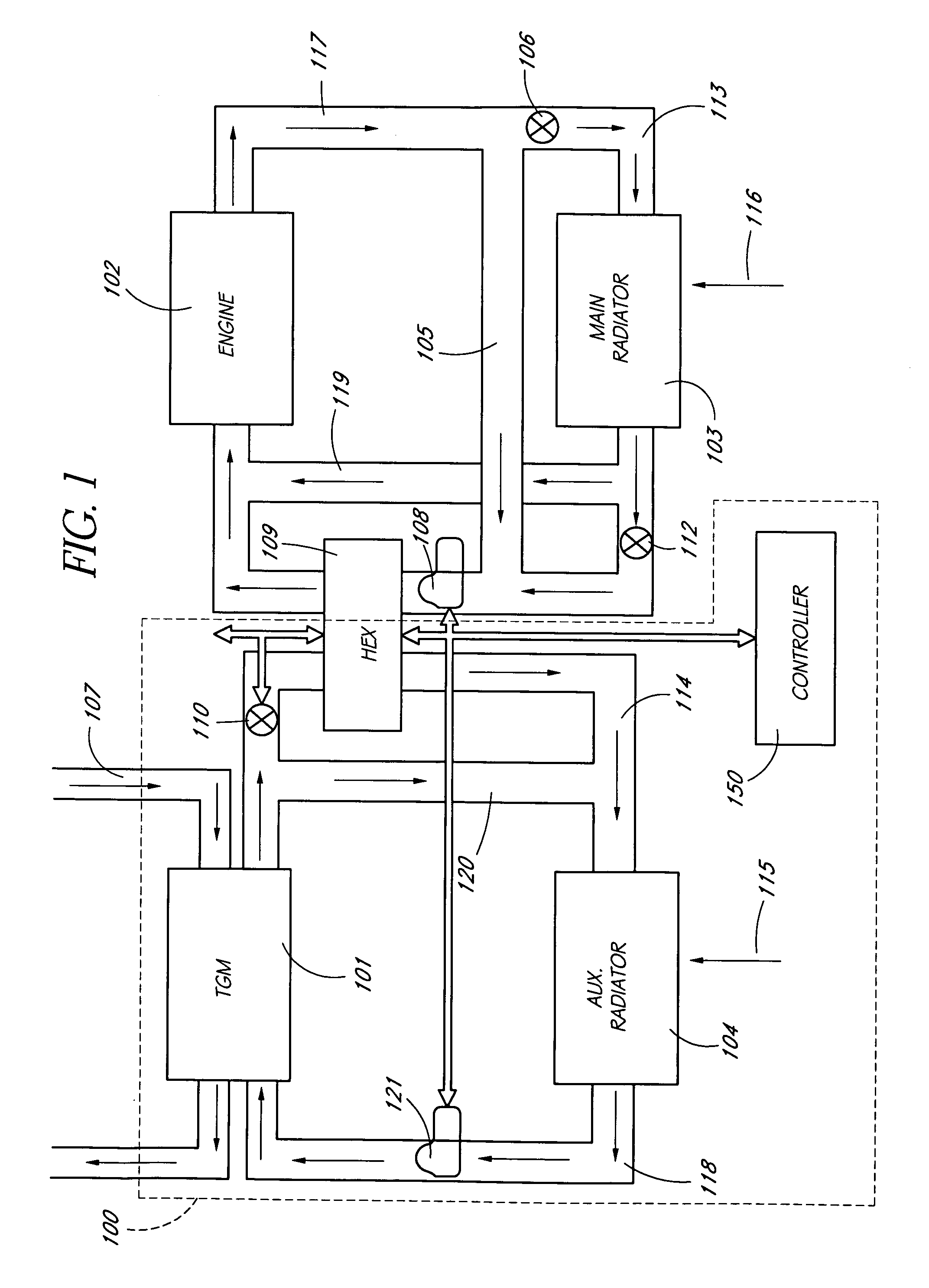
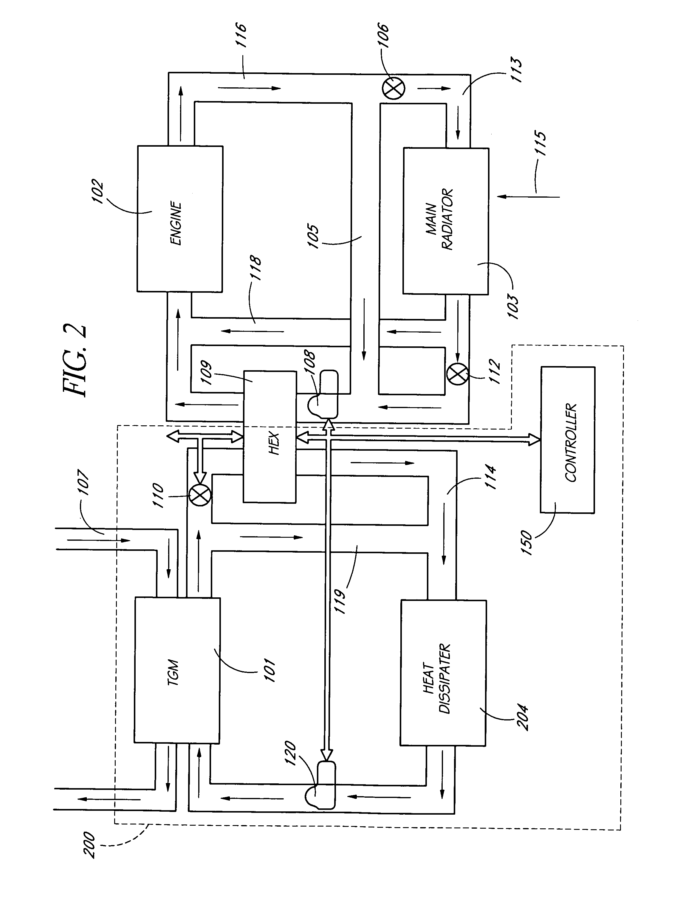
[0025]Automotive waste heat recovery is used as an example of the present invention. However, the invention is applicable to improve the performance of power generation, waste heat recovery, cogeneration, power production augmentation, and other uses. As further examples, the present invention can be used to utilize waste heat in the engine coolant, transmission oil, brakes, catalytic converters, and other sources in cars, trucks, busses, trains, aircraft and other vehicles. Similarly, waste heat from chemical processes, glass manufacture, cement manufacture, and other industrial processes can be utilized. Other sources of waste heat such as from biowaste, trash incineration, burn off from refuse dumps, oil well burn off, can be used. Power can be produced from solar, nuclear, geothermal and other heat sources. Application to portable, primary, standby, emergency, remote, personal and other power production devices are also part of this invention. In addition, the present invention ...


PUM


Abstract

A thermoelectric power generator is disclosed for use to generate electrical power from heat, typically waste heat. An intermediate heat transfer loop forms a part of the system to permit added control and adjustability in the system. This allows the thermoelectric power generator to more effectively and efficiently generate power in the face of dynamically varying temperatures and heat flux conditions, such as where the heat source is the exhaust of an automobile, or any other heat source with dynamic temperature and heat flux conditions.

Description

CROSS-REFERENCE TO RELATED APPLICATIONS[0001]This application relates to and claims the benefit of priority of U.S. Provisional Patent Application No. 60 / 694,746 entitled “High-Efficiency Thermoelectric Waste Energy Recovery System for Passenger Vehicle Applications,” filed Jun. 28, 2005.STATEMENT REGARDING FEDERALLY SPONSORED R&D[0002]The U.S. Government may claim to have certain rights in this invention or parts of this invention under Contract No. DE-FC26-04NT42279 awarded by the U.S. Department of Energy.BACKGROUND OF THE INVENTION[0003]1. Field of the Invention[0004]The present application relates to the field of thermoelectric power generation, and more particularly to systems for improving the generation of power from thermoelectrics, particularly in the situation where there are limitations in the system on the temperature differential across the thermoelectric.[0005]2. Description of the Related Art[0006]Thermoelectrics are solid state devices that operate to become cold on...

Claims


Application Information

Patent Timeline
Patent Type & Authority Patents(United States)
IPC IPC(8): H01L35/00H01L35/28H01L35/30
CPCF01P9/06H01L35/30F01P2011/205Y02E20/14F02G2260/00H10N10/13
Inventor BELL, LON E.CRANE, DOUGLAS TODD
Owner GENTHERM INC
Why Eureka
Try Eureka