Power generation system and method for storing electrical energy

a power generation system and electrical energy technology, applied in the direction of electric generator control, dynamo-electric converter control, machines/engines, etc., can solve the problem that the control system reduces the amount of electrical power generated by the wind turbin

Active Publication Date: 2009-10-27
GENERAL ELECTRIC CO
View PDF9 Cites 61 Cited by
  • Summary
  • Abstract
  • Description
  • Claims
  • Application Information

AI Technical Summary

Benefits of technology

[0003]A power generation system in accordance with an exemplary embodiment is provided. The power generation system includes a power converter having a housing, a rectifier, a DC voltage bus, an inverter, and a power converter controller. The rectifier, the DC voltage bus, the inverter and the power converter controller are disposed in the housing. The DC voltage bus is electrically coupled to both the rectifier and the inverter. The controller operably communicates with the inverter. The rectifier is configured to receive a first AC voltage and to convert the first AC voltage to a first DC voltage. The DC voltage bus is configured to route the first DC voltage to the inverter. The inverter is configured to convert the first DC voltage to a second AC voltage and to output the second AC voltage to an electrical grid in response to a first control signal from the power converter controller. The power generation system further includes a DC-DC converter operably coupled to the DC voltage bus. The DC-DC converter is configured to receive the first DC voltage from the DC voltage bus and to store electrical energy from the first DC voltage in a battery storage unit in response to a second control signal. The DC-DC converter is further configured to output a second DC voltage that is routed through the DC voltage bus to the inverter in response to a third control signal. The inverter of the power converter is further configured to convert the second DC voltage to a third AC voltage and to output the third AC voltage on the electrical grid in response to a fourth control signal from the power converter controller.

Problems solved by technology

However, when the wind farms begin generating excess electrical power that is not needed by an electrical grid, a control system reduces an amount of electrical power generated by the wind turbines.

Method used


Image

  • Power generation system and method for storing electrical energy
  • Power generation system and method for storing electrical energy
  • Power generation system and method for storing electrical energy

Examples


Embodiment Construction

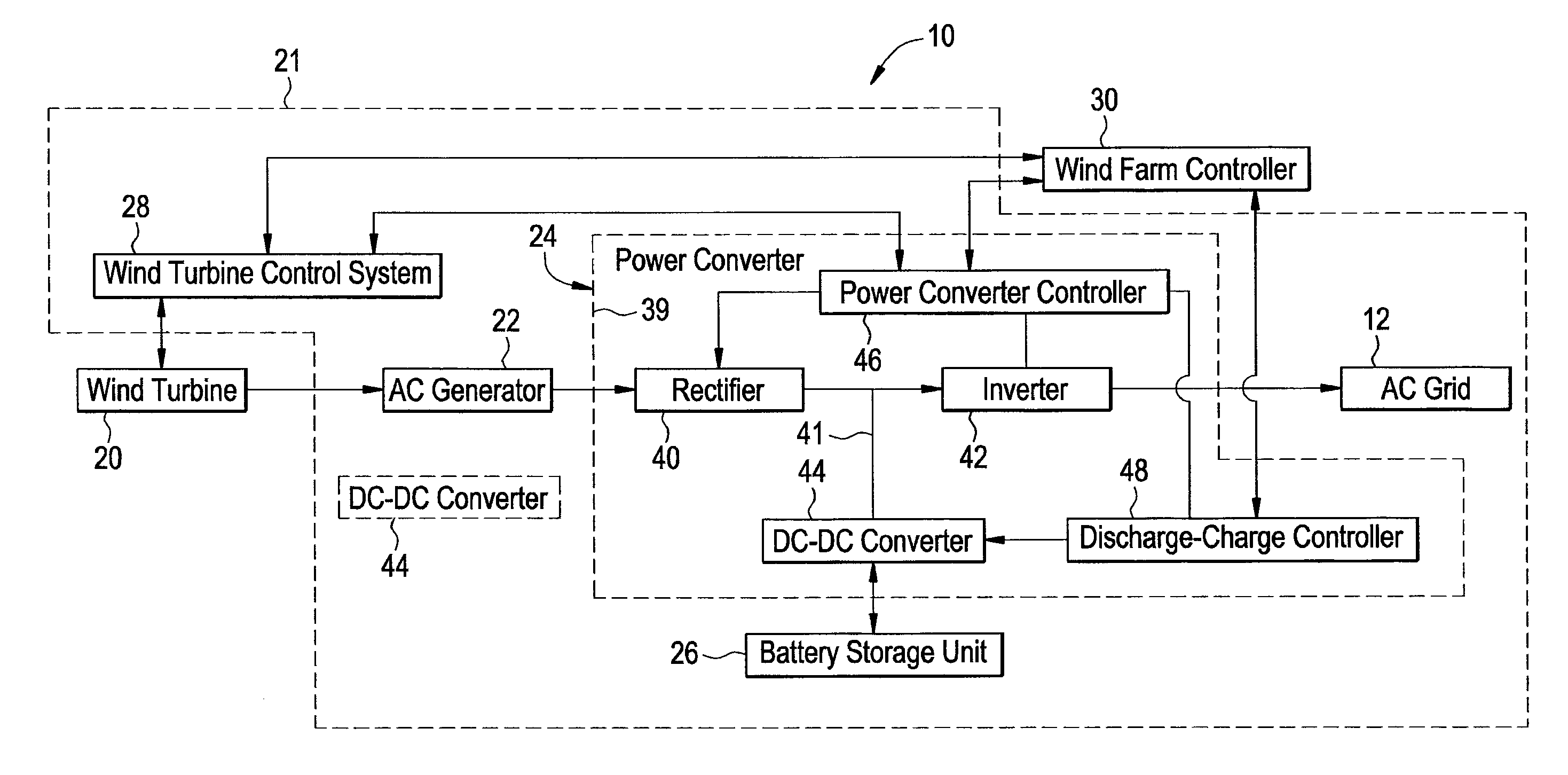
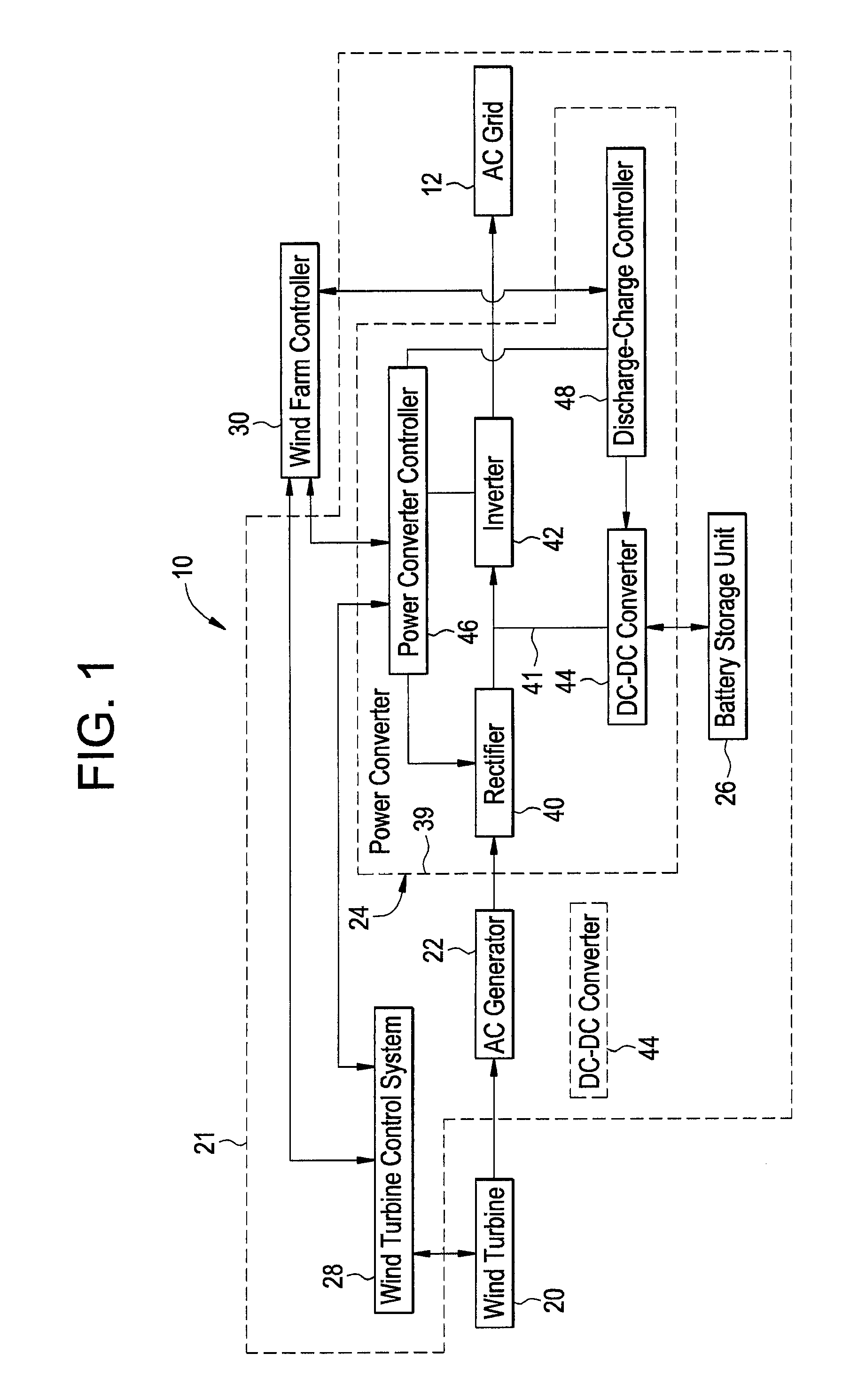
[0007]Referring to FIG. 1, a wind farm power generation system 10 for delivering electrical power to the AC electrical grid 12 will now be explained. The wind farm power generation system 10 includes a wind turbine 20, a wind turbine housing 21, an AC generator 22, a power converter 24, a battery storage unit 26, a wind turbine control system 28, and a wind farm controller 30.

[0008]The wind turbine 20 is configured to rotate in response to wind contacting the wind turbine 20 to drive the AC generator 22 such that the AC generator 22 outputs an AC voltage. The wind turbine 20 is operably coupled to the wind turbine controller 28 which can control operation of the wind turbine 20.

[0009]The wind turbine housing 21 is configured to enclose the AC generator 22, the power converter 24, the battery storage unit 26, and the wind turbine controller 28 therein. The wind turbine 20 is rotatably coupled to the wind turbine housing 21.

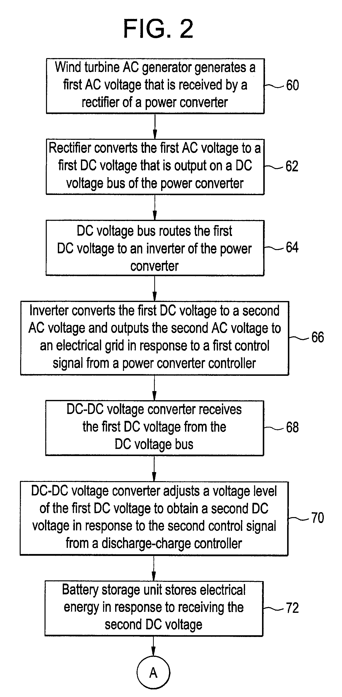
[0010]The power converter 24 is configured to receive the AC ...


PUM


Abstract

A power generation system and a method for storing electrical energy are provided. The method includes generating a first AC voltage from a wind turbine generator and converting the first AC voltage to a first DC voltage, utilizing a rectifier. The method further includes routing the first DC voltage through a DC voltage bus to an inverter of the power converter, and converting the first DC voltage to a second AC voltage utilizing the inverter and outputting the second AC voltage to an electrical grid in response to a first control signal from a power converter controller. The method further includes receiving the first DC voltage from the DC voltage bus at a DC-DC converter operably coupled to the DC voltage bus, and storing electrical energy from the first DC voltage in a battery storage unit utilizing the DC-DC converter in response to a second control signal.

Description

BACKGROUND OF THE INVENTION[0001]Wind farms have been utilized to generate electrical power. The wind farms typically have a plurality of wind turbines each generating electrical power. However, when the wind farms begin generating excess electrical power that is not needed by an electrical grid, a control system reduces an amount of electrical power generated by the wind turbines. Accordingly, a total amount of electrical power that the wind turbines are capable of generating is not utilized.[0002]Accordingly, the inventor herein has recognized a need for an improved power generation system that minimizes and / or eliminates the above mentioned deficiency.BRIEF DESCRIPTION OF THE INVENTION[0003]A power generation system in accordance with an exemplary embodiment is provided. The power generation system includes a power converter having a housing, a rectifier, a DC voltage bus, an inverter, and a power converter controller. The rectifier, the DC voltage bus, the inverter and the power...

Claims


Application Information

Patent Timeline
Patent Type & Authority Patents(United States)
IPC IPC(8): F03D9/00H02P11/00H02P9/04
CPCH02J7/34H02J3/386Y02E10/725Y02E10/766Y02E10/763H02J2300/28H02J3/381Y02E10/72Y02E10/76
Inventor ALTENSCHULTE, MARKUS
Owner GENERAL ELECTRIC CO
Why Eureka
Try Eureka