Linear ion accelerator

a linear ion accelerator and accelerator technology, applied in the direction of instruments, mass spectometers, beam deviation/focusing by electric/magnetic means, etc., can solve problems such as length reduction problems, and achieve the effect of reducing the total length and high energy level

Active Publication Date: 2009-10-27
MITSUBISHI ELECTRIC CORP
View PDF3 Cites 40 Cited by
  • Summary
  • Abstract
  • Description
  • Claims
  • Application Information

AI Technical Summary

Benefits of technology

[0012]As described above in (1), for a conventional APF linear ion accelerator, since the acceleration electric field for each acceleration gap can not be increased, an increase in the number of drift tubes, i.e., the number of acceleration gaps, is required in order to accelerate the ion beam until a predetermined high energy has been attained. As a result, the ion beam must be accelerated slowly using a long linear ion accelerator. Therefore, the affect produced by the space charge effect is increased, and the divergence of the ion beam becomes great during the acceleration period. Especially for proton, since the ratio of the mass to charges is small, the space charge effect is great, and the high current acceleration of a proton beam is difficult until a high energy has been reached.
[0016]Since this arrangement is employed for the APF linear ion accelerator of the aspect of the invention, the total length can be reduced, compared with a conventional APF linear ion accelerator, and an ion beam having a higher current can be accelerated until a high energy level is reached.

Problems solved by technology

However, in this instance, for an APF linear ion accelerator, there exist the following problems, which also include an accelerator length reduction and a high current acceleration and, especially, when the object is the acceleration of proton, the availability of an accelerator acceptable for practical use, one of which has yet to be developed.
Essentially, this constitutes a length reduction problem for which a solution is expeditiously required.

Method used


Image

  • Linear ion accelerator
  • Linear ion accelerator
  • Linear ion accelerator

Examples


first embodiment

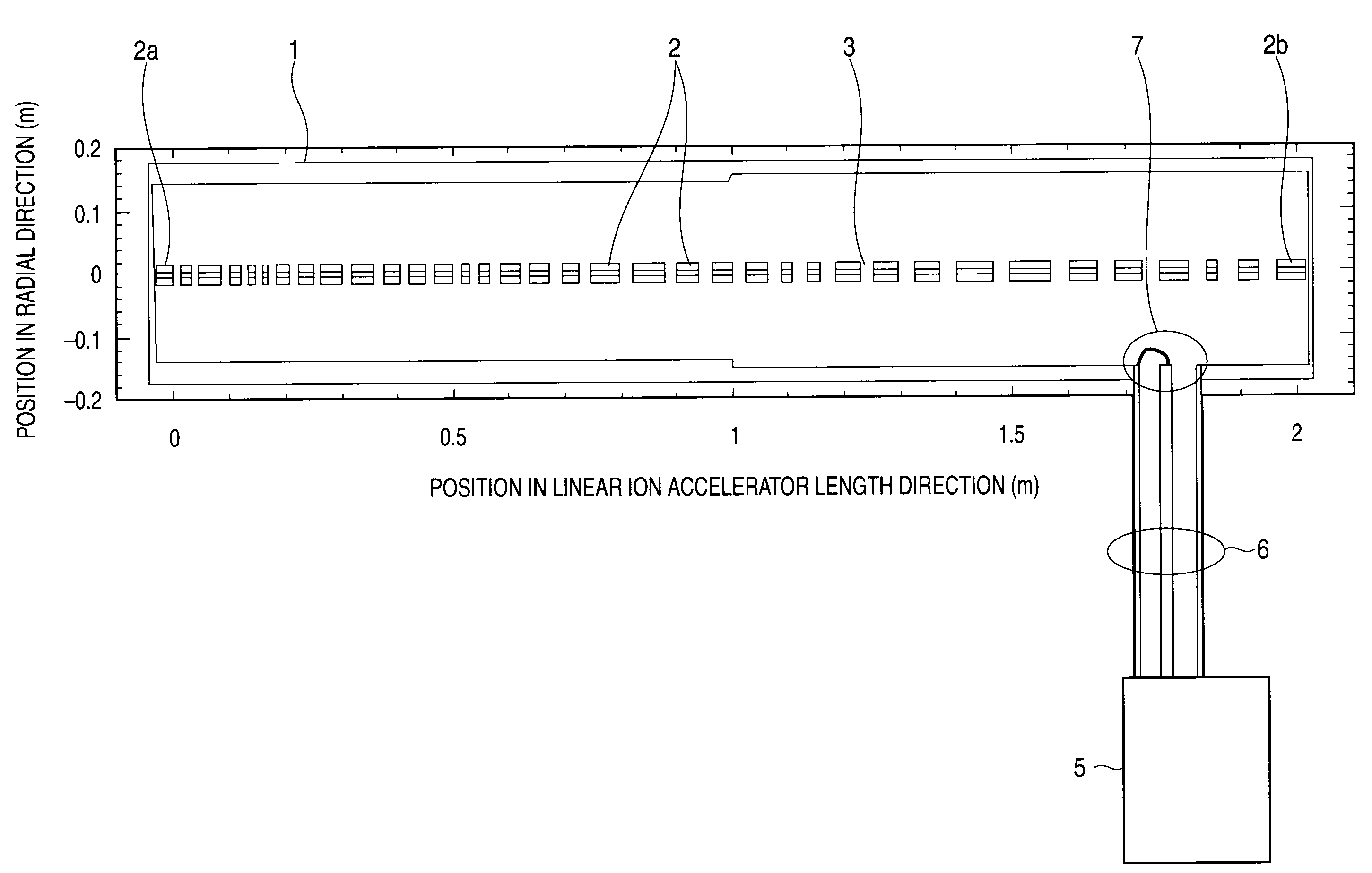
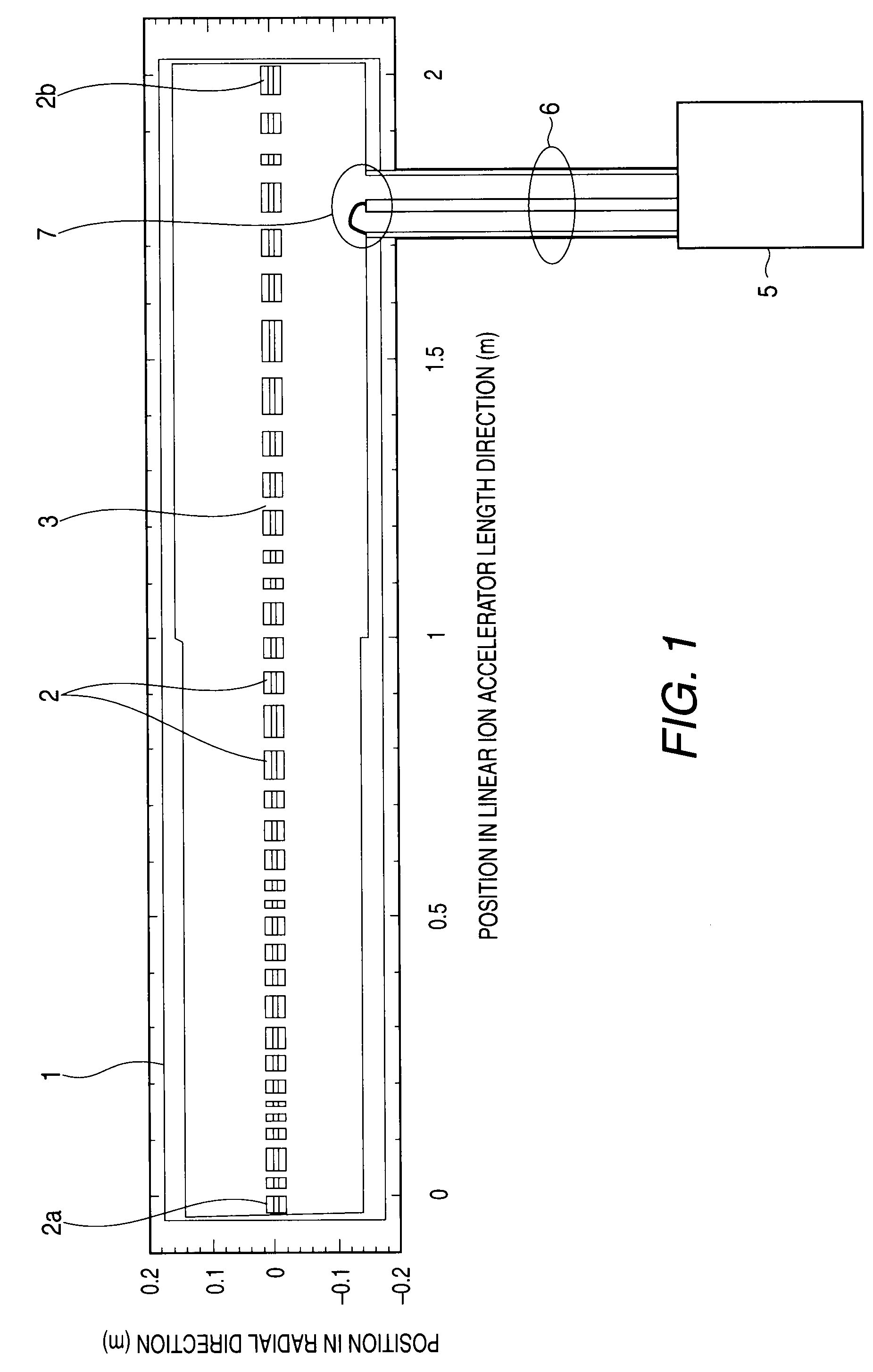
[0024]FIG. 1 is a cross sectional view of the concept of an APF linear ion accelerator according to a first embodiment of the present invention. In FIG. 1, the horizontal axial direction represents the direction of the length of the APF linear ion accelerator (or the central axial direction), the vertical axial direction represents a direction perpendicular to the central axial direction of the linear ion accelerator, and numerical values provided for the vertical axis and the horizontal axis are example values representing locations in the individual directions using the unit of the meter. An acceleration cavity 1 is used to confine a radio frequency electric field, and a plurality of cylindrical electrodes 2, called drift tubes, are arranged, in the manner as shown in FIG. 1, along the central axis of the acceleration cavity 1 (the horizontal axis that runs across 0 of the scale for the vertical axis in FIG. 1). The number of the cylindrical electrodes becomes sometimes from sever...


PUM


Abstract

The electrode lengths of a plurality of electrodes linearly arranged in an acceleration cavity are proportional to the velocity of a traveling ion beam. Further, the electrode length is so designated that, in each half of a predetermined cycle in the ion beam direction of travel, the absolute value of a difference, relative to a length that is proportional to the beam traveling velocity is equal to or greater than a value corresponding to the phase width of the traveling ion beam, is provided for electrodes that do not exceed three units and that are fewer than electrodes allotted to half the predetermined cycle.

Description

BACKGROUND OF THE INVENTION[0001]1. Field of the Invention[0002]The present invention relates to an APF (Alternating-Phase-Focused) linear ion accelerator that accelerates an ion beam, such as a carbon beam or a proton beam, to obtain the ion beam of high energy.[0003]2. Description of the Background Art[0004]An APF linear ion accelerator includes an acceleration cavity in which a plurality of cylindrical electrodes called drift tubes (hereinafter referred to simply as drift tubes) are arranged along the linear path of an ion beam that is injected into the acceleration cavity, so that the lengths of the drift tubes are changed sinusoidally, in consonance with a predetermined cycle, in the direction in which the ion beam passes. This change in tube lengths is hereinafter called an oscillation having a predetermined cycle. Furthermore, gaps are formed between the drift tubes, while a radio frequency acceleration electric field is applied to the individual gaps. Thereafter, when an ion...

Claims


Application Information

Patent Timeline
Patent Type & Authority Patents(United States)
IPC IPC(8): H05H9/00H01J27/00
CPCH05H9/00H05H7/22
Inventor TANAKA, HIROFUMIYAMAMOTO, KAZUOHARADA, HISASHIINOUE, HIROMITSUNAGAYAMA, TAKAHISAZUMOTO, NOBUYUKI
Owner MITSUBISHI ELECTRIC CORP
Why Eureka
Try Eureka