
Multiple status e-fuse based non-volatile voltage control oscillator configured for process variation compensation, an associated method and an associated design structure

a voltage control and oscillator technology, applied in the frequency range of voltage control oscillators, pulse automatic control, oscillator generators, etc., can solve the problems of affecting the operational frequency range, no longer within,

Inactive Publication Date: 2009-10-27
INT BUSINESS MASCH CORP
View PDF11 Cites 7 Cited by
  • Summary
  • Abstract
  • Description
  • Claims
  • Application Information

AI Technical Summary

Benefits of technology

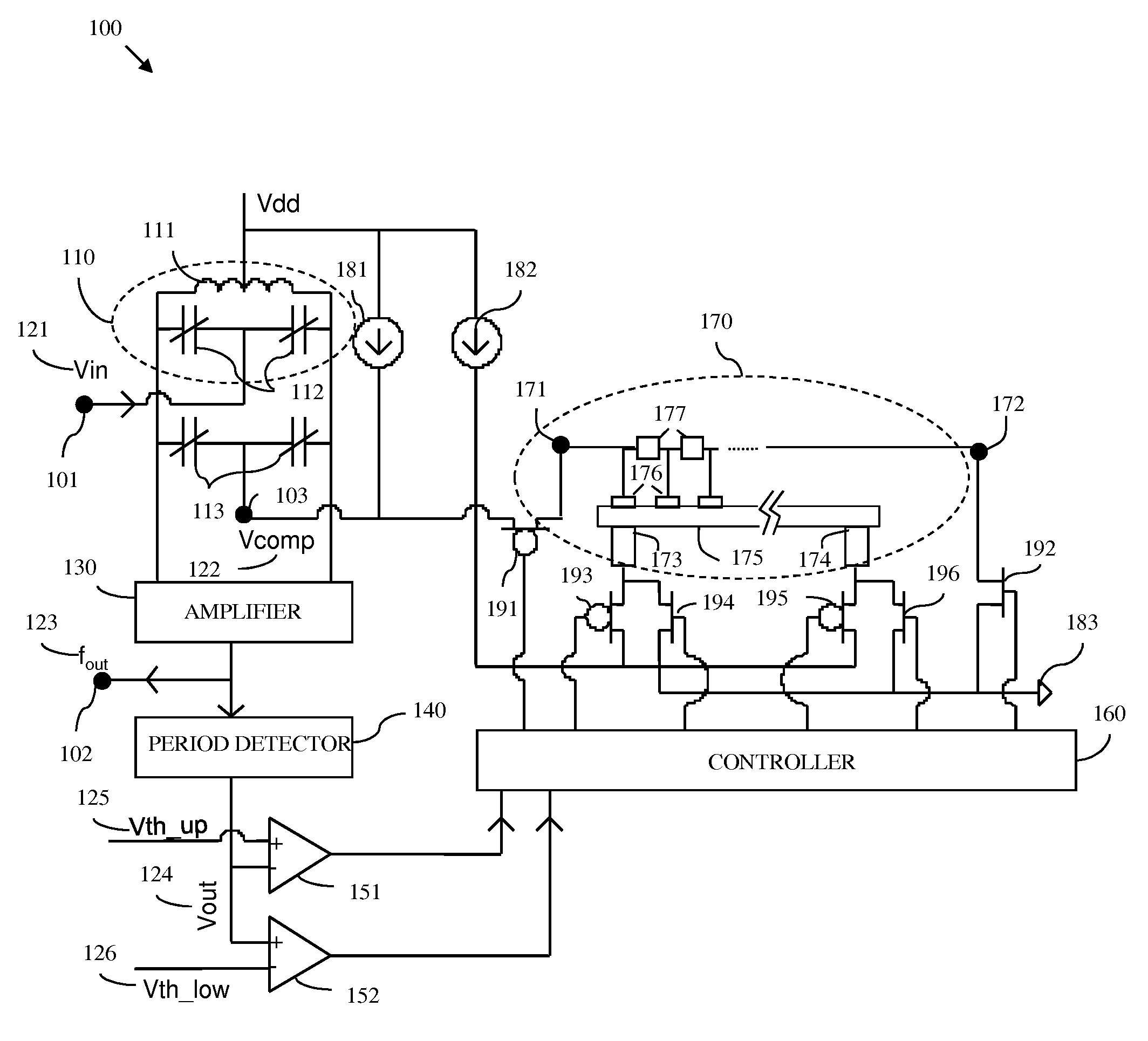
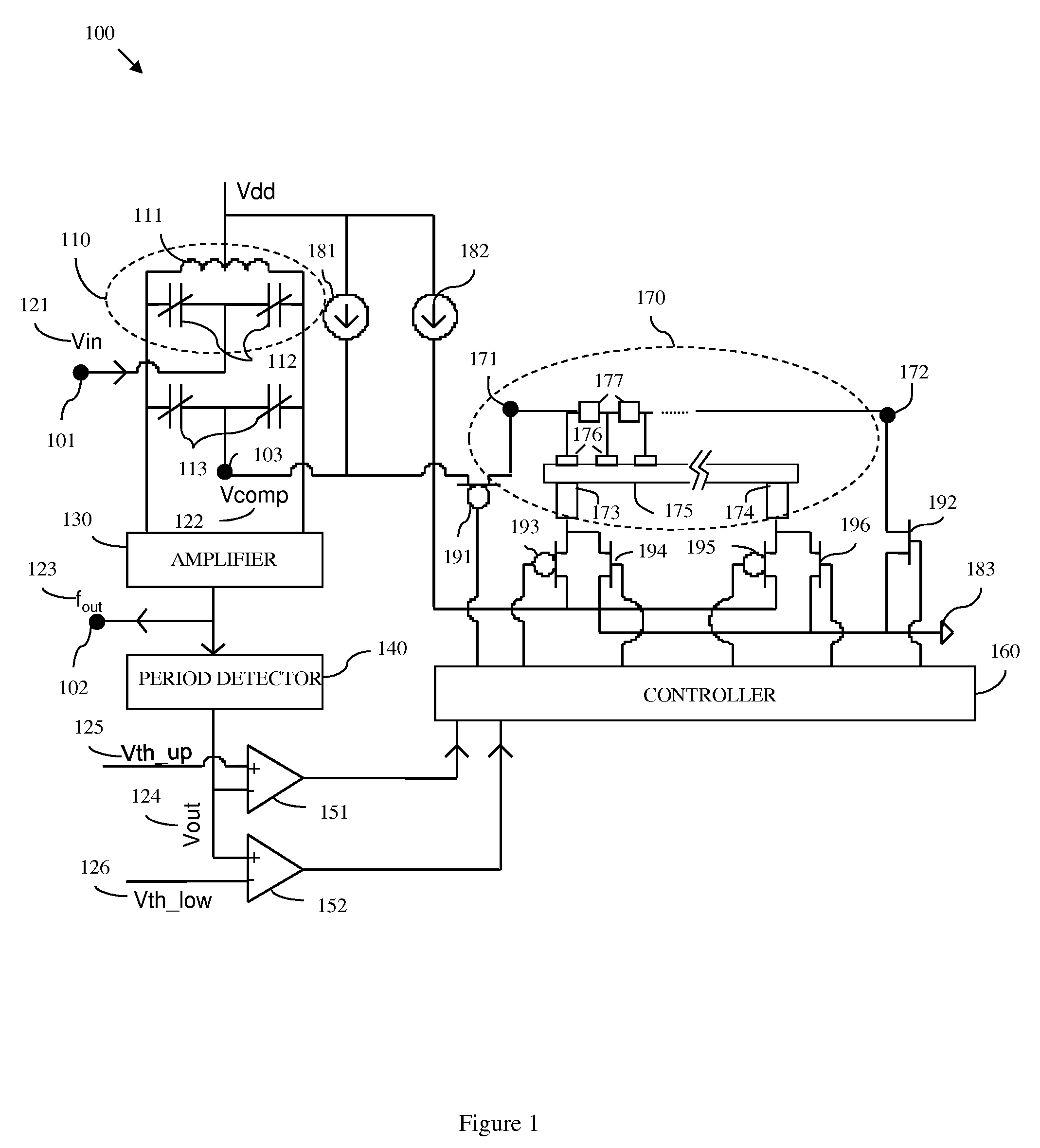
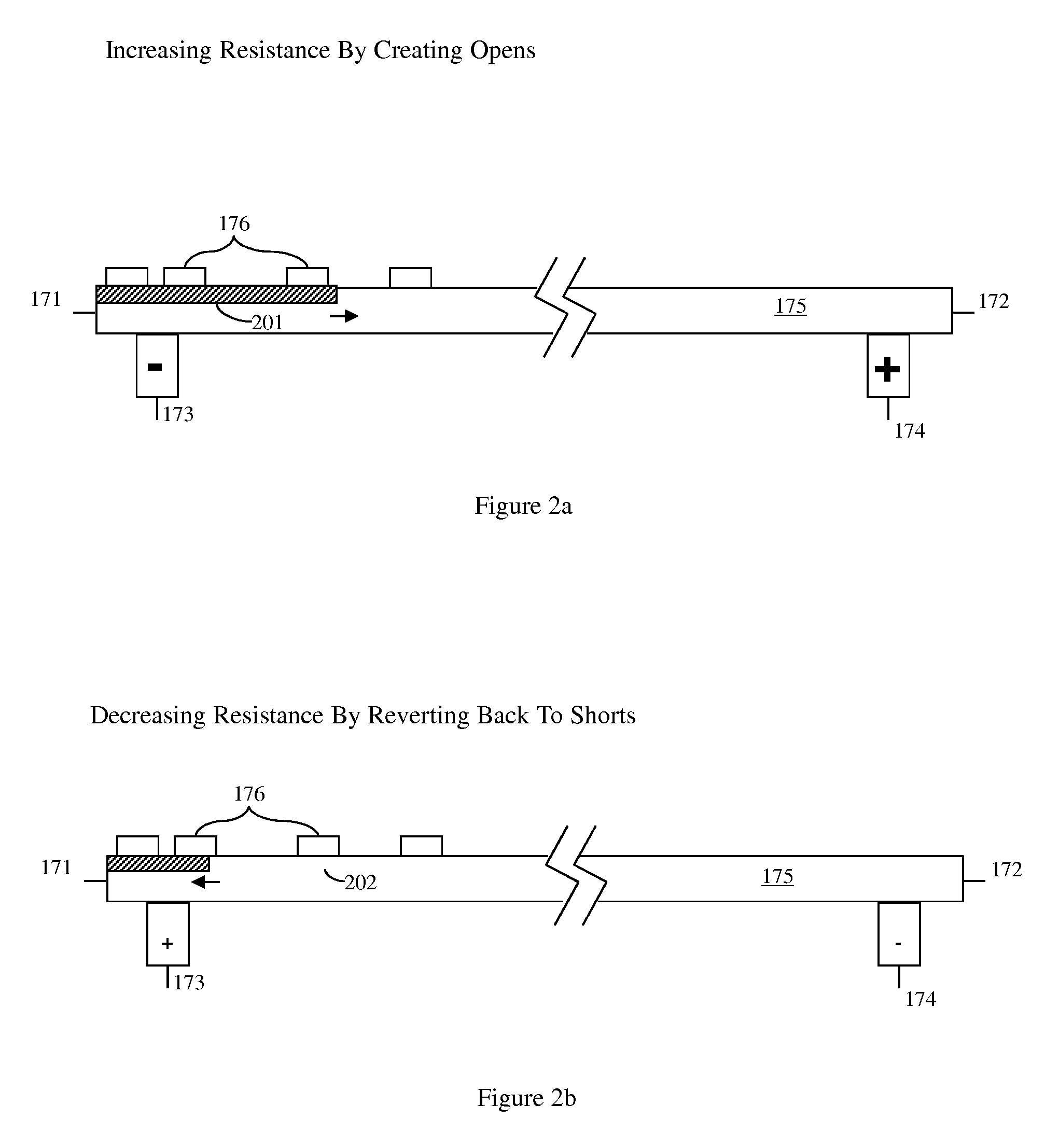
[0013]The embodiments of the voltage controlled oscillator are described above as incorporating only a single variable resistance e-fuse. Alternatively, the voltage controlled oscillator can comprise a plurality of such variable resistance e-fuses. Specifically, multiple variable resistance e-fuses can be connected in series. In this case, all of the resistors in any given variable resistance e-fuse will be equal in size. However, the resistors on adjacent variable resistance e-fuses will be progressively smaller in size. Such a structure allows for fine tuning of the frequency the periodic signal at the output node because each subsequent e-fuse can be programmed in order to make smaller incremental changes in overall resistance and, thereby to make smaller incremental changes to the compensation voltage applied to the varactor(s).
[0019]The embodiments of the method are described above as including a programming step for only one variable resistance e-fuse. Alternatively, the voltage controlled oscillator can comprise a plurality of such variable resistance e-fuses. Specifically, multiple variable resistance e-fuses can be connected in series. In this case, all of the resistors in any given variable resistance e-fuse will be equal in size. However, the resistors on adjacent variable resistance e-fuses will be progressively smaller in size. Such a structure allows for fine tuning of the frequency the periodic signal at the output node because each subsequent e-fuse can be programmed in order to make smaller incremental changes in overall resistance and, thereby to make smaller incremental changes to the compensation voltage applied to the varactor(s).

Problems solved by technology

Specifically, with continued device scaling, process variations can impact the operational frequency range of a VCO such that it is no longer within specification.

Method used


Image

  • Multiple status e-fuse based non-volatile voltage control oscillator configured for process variation compensation, an associated method and an associated design structure
  • Multiple status e-fuse based non-volatile voltage control oscillator configured for process variation compensation, an associated method and an associated design structure
  • Multiple status e-fuse based non-volatile voltage control oscillator configured for process variation compensation, an associated method and an associated design structure

Examples


Embodiment Construction

[0030]The embodiments of the invention and the various features and advantageous details thereof are explained more fully with reference to the non-limiting embodiments that are illustrated in the accompanying drawings and detailed in the following description. It should be noted that the features illustrated in the drawings are not necessarily drawn to scale. Descriptions of well-known components and processing techniques are omitted so as to not unnecessarily obscure the embodiments of the invention. The examples used herein are intended merely to facilitate an understanding of ways in which the embodiments of the invention may be practiced and to further enable those of skill in the art to practice the embodiments of the invention. Accordingly, the examples should not be construed as limiting the scope of the embodiments of the invention.

[0031]As mentioned above, process variations impact performance in all technologies. In voltage controlled oscillators (VCOs) such process varia...


PUM


Abstract

Disclosed are embodiments of a voltage controlled oscillator (VCO) capable of non-volatile self-correction to compensate for process variations and to ensure that the center frequency of the oscillator is maintained within a predetermined frequency range. This VCO incorporates a pair of varactors connected in parallel to an inductor-capacitor (LC) tank circuit for outputting a periodic signal having a frequency that is proportional to an input voltage. A control loop uses a programmable variable resistance e-fuse to set a compensation voltage to be applied to the pair of varactors. By adjusting the compensation voltage, the capacitance of the pair of varactors can be adjusted in order to selectively increase or decrease the frequency of the periodic signal in response to a set input voltage and, thereby to bring the frequency of that periodic signal into the predetermined frequency range. Also disclosed are embodiments of an associated design structure for such a VCO and an associated method for operating such a VCO.

Description

BACKGROUND OF THE INVENTION[0001]The embodiments of the invention generally relate to the frequency range of voltage control oscillators (VCOs) and, more particularly, to a VCO configured with a control loop that incorporates variable resistance e-fuse(s) to selectively adjust the periodic output signal frequency to compensate the process variation. The embodiments also relate to an associated design structure for such a VCO and to an associated method for operating such a VCO.DESCRIPTION OF THE RELATED ART[0002]Process variations impact performance in all technologies. In voltage controlled oscillators (VCOs) such process variations can have a significant impact on operation frequency. Specifically, with continued device scaling, process variations can impact the operational frequency range of a VCO such that it is no longer within specification. Therefore, it would be advantageous to provide a VCO capable of non-volatile self-correction to compensate for process variations and, th...

Claims


Application Information

Patent Timeline
Patent Type & Authority Patents(United States)
IPC IPC(8): H03B5/12H03L7/099
CPCH03B5/1206H03B5/1243
Inventor FENG, KAI D.LAI, KAFAIWANG, PING-CHUANYANG, ZHIJIAN J.
Owner INT BUSINESS MASCH CORP
Learn More