Optical beam scanning device, optical beam scanning method
a scanning device and optical beam technology, applied in the field of optical beam scanning devices, can solve the problems of insufficient suppression of the defocus change amount at the time of temperature change, the inability to achieve objects, and the inability to change the optical path in the sub-scanning direction
- Summary
- Abstract
- Description
- Claims
- Application Information
AI Technical Summary
Benefits of technology
Problems solved by technology
Method used
Image


Examples
example
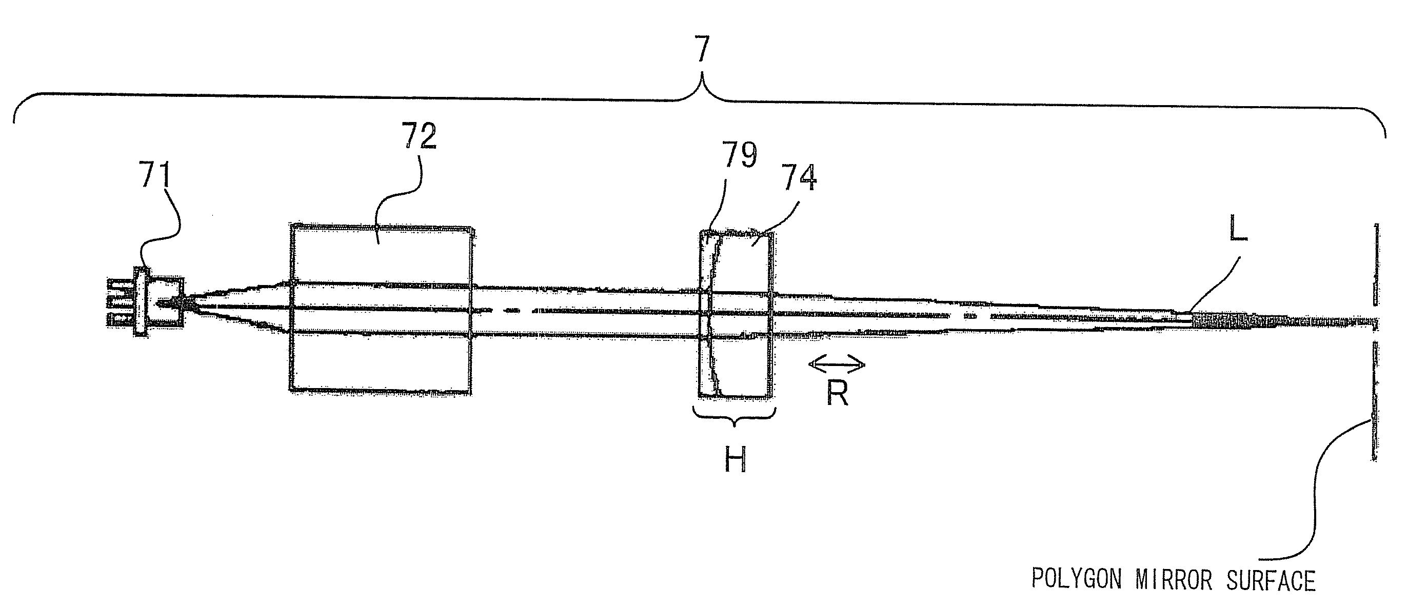
[0110]Next, specific examples of the invention will be described. In the respective examples described below, a description will be given to examples in which the optical system has the structure including two fθ lenses shown in FIG. 1 and FIG. 3.
[0111]In the case where[0112]material of an optical system housing: alumina die casting (linear expansion coefficient αH=2.1×10⁻⁵),[0113]material regulating an interval between photosensitive bodies: alumina die casting (linear expansion coefficient αF=2.1×10⁻⁵),[0114]material of a drive shaft of a transfer belt: alumina die casting (linear expansion coefficient αs=2.1×10⁻⁵),[0115]interval between light beams incident on photosensitive bodies (photosensitive body 401k and photosensitive body 401y) at both ends: L=225 mm, and[0116]temperature rise: t=15 degrees,[0117]an ideal change amount of distance between beams at both ends in the sub-scanning direction is
−(αH−2×αF+αs)×(L×t)+αH×LB×t=0+0.007=0.007 (21)
(this means that in the case where ...
PUM
 Abstract
Description
Claims
Application Information