
Ad hoc communications system

a communication system and ad hoc technology, applied in the field of ad hoc networking applications, can solve problems such as the change of nearest neighbours between data transmissions

Inactive Publication Date: 2009-10-27
BRITISH TELECOMM PLC
View PDF19 Cites 22 Cited by
  • Summary
  • Abstract
  • Description
  • Claims
  • Application Information

AI Technical Summary

Benefits of technology

[0051]Although they would reduce the power consumption required for transmission, directional antennas would therefore be difficult to accommodate and control in very small devices. In a preferred embodiment each wireless relay device has an address code to which data intended for that device should be sent. This address code may be a digital code, for example a CDMA chopping code. It may instead be a radio frequency or time slot allocated to that device on which it will listen out. Each device broadcasts its address code as well as its position and other attributes. Thus any neighbour selecting it, according to its direction and distance, as a target to which payload data should be transmitted can identify it by specifying its address. Each device is arranged to only receive data directed to its own address. Given that battery power considerations impose a relatively limited transmission range on the devices, addresses may be duplicated provided that the probability of two duplicate addresses occurring within range of a single transmitting device is low.
[0062]The invention allows the collection of data from an ad hoc network of highly mobile sensor devices, to one or more “sink” devices, which may also be mobile, in a way that is distributed, robust and lightweight.

Problems solved by technology

Because the devices are moving rapidly, even their nearest neighbours may change between data transmissions.

Method used


Image

  • Ad hoc communications system
  • Ad hoc communications system
  • Ad hoc communications system

Examples


Embodiment Construction

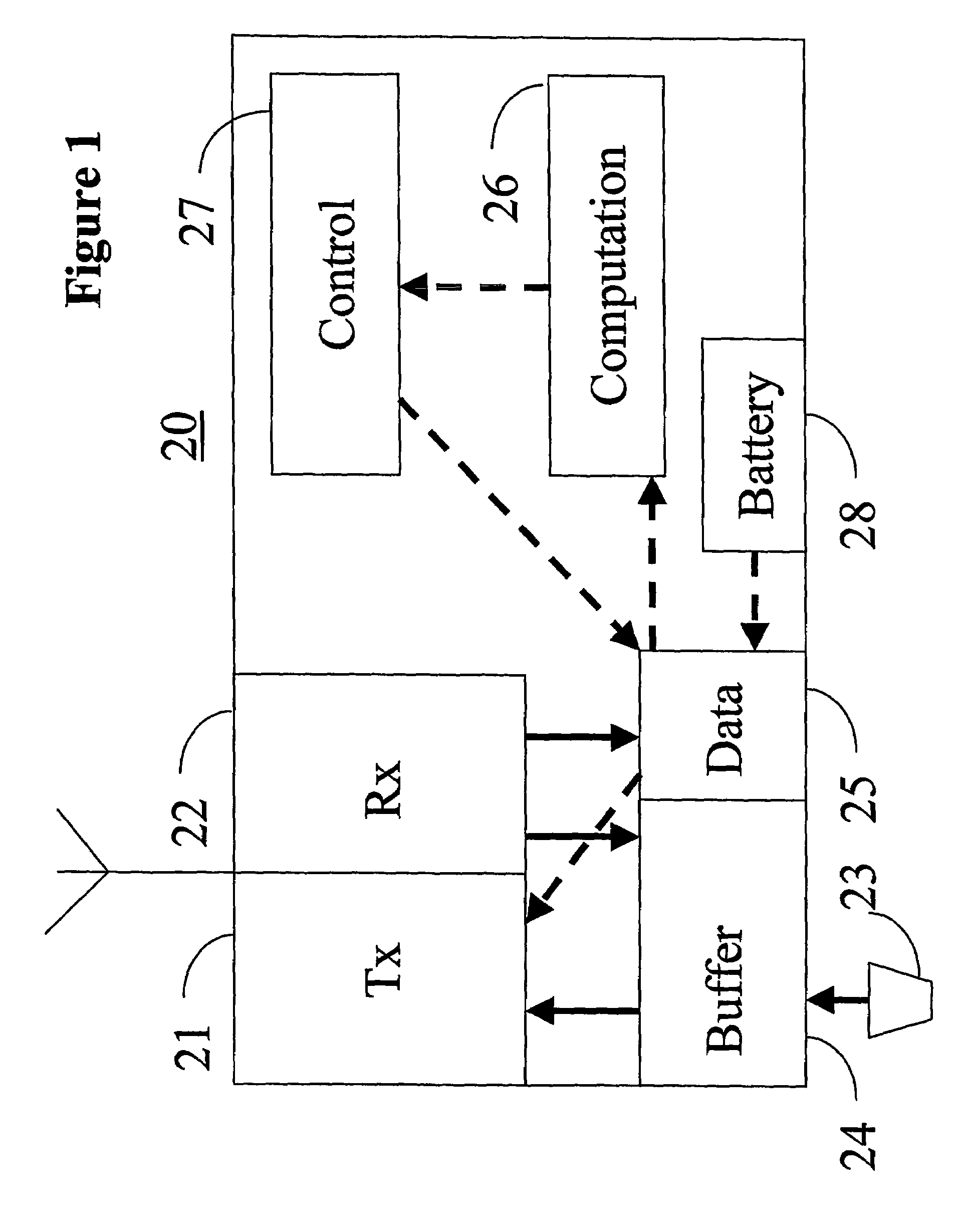
[0069]FIG. 1 shows a device 20 according to the invention. It comprises a wireless transmitter 21 and a wireless receiver 22, and data collection means 23 which include position sensors, and environmental or physiological sensors for determining properties of the environment of the device, or of some object to which it is attached. There is also a data buffer 24 for storing payload data (that is to say, data that is to be transmitted to a destination for processing) and a data store 25 for operational data (that is to say, data required for the operation of the device and in particular for controlling the transmission of the payload data). There is also computation means 26 for processing the data collected by the data collection means 23 and stored in the data buffer 24, and control means 27 for controlling the operation of the device in response to outputs from the computation means 26. The device is powered by a battery 28 whose condition is monitored and the results stored in th...


PUM


Abstract

A number of data collection devices are free to move relative to each other through their environment, collecting data from their environment. They form an ad hoc wireless network in which data collected by a device either by its own sensors, or relayed from another device is transmitted to a destination either directly or by means of one or more other devices. The destination collects data collected by the mobile terminals for subsequent processing. The wireless links between them have to be re-arranged in order to provide the optimum network. When two devices come into proximity to each other, a forwarding direction is determined to identify to which device data should be forwarded. The devices co-operate to define their forwarding directions by exchanging data relating to their physical locations, and factors such as the spare capacity of their buffer stores, and battery condition. Thus a network will be defined dynamically, each device having its forwarding direction aimed in the direction of the next device until they reach a sink.

Description

CROSS-REFERENCE TO RELATED APPLICATIONS[0001]This application is the US national phase of international application PCT / GB2004 / 001999 filed 7 May 2004 which designated the U.S. and claims benefit of GB 0315758.3, dated 4 Jul. 2003 and GB 0315969.6, dated 8 Jul. 2003, the entire content of which is hereby incorporated by reference.BACKGROUND[0002]1. Technical Field[0003]This invention relates to ad hoc networking application, in which a number of communications devices co-operate to form a communications network.[0004]2. Related Art[0005]There are two basic types, namely many-to-many communication, wherein the devices communicate with conventional fixed networks through interface or edge devices. The communications devices form nodes of a wireless network, allowing data to be relayed from an originating communications device to a destination communications device, by way of other communications devices. Such devices have a number of applications in circumstances where the communicati...

Claims


Application Information

Patent Timeline
Patent Type & Authority Patents(United States)
IPC IPC(8): H04L12/54H04L12/56
CPCH04L45/02H04W40/02H04W84/22
Inventor TATESON, JANE E
Owner BRITISH TELECOMM PLC
Learn More