
Reception of a signal modulated according to a multilevel coding technique

Active Publication Date: 2009-10-27
TDF CORP
View PDF9 Cites 57 Cited by
  • Summary
  • Abstract
  • Description
  • Claims
  • Application Information

AI Technical Summary

Benefits of technology

[0030]More specifically, it is a goal of the invention to provide a technique for the decoding of a signal modulated according to an MLC coding technique, having improved performance compared with the prior art techniques.
[0031]It is another goal of the invention to implement such a technique, that enables a reduction in the binary error rate (or BER) as compared with the sub-optimal decoding technique of the prior art.
[0032]It is also a goal of the invention to provide a technique of this kind that is simple and costs little to implement, and is suited to disturbance-prone channels, and especially to channels showing Gaussian additive noise and Doppler-affected multiple-path channels.

Problems solved by technology

However, in applications of high-capacity RF beams, the implementation of the Viterbi decoder, which is necessary to decode the modulation, is still very costly.
Such codes are simpler to implement, but their coding gain is generally limited to 2 dB.
Now, for an MLC to be optimal, the decoding gain that must be obtained between the different coding levels is 6 dB, which is very difficult to obtain.
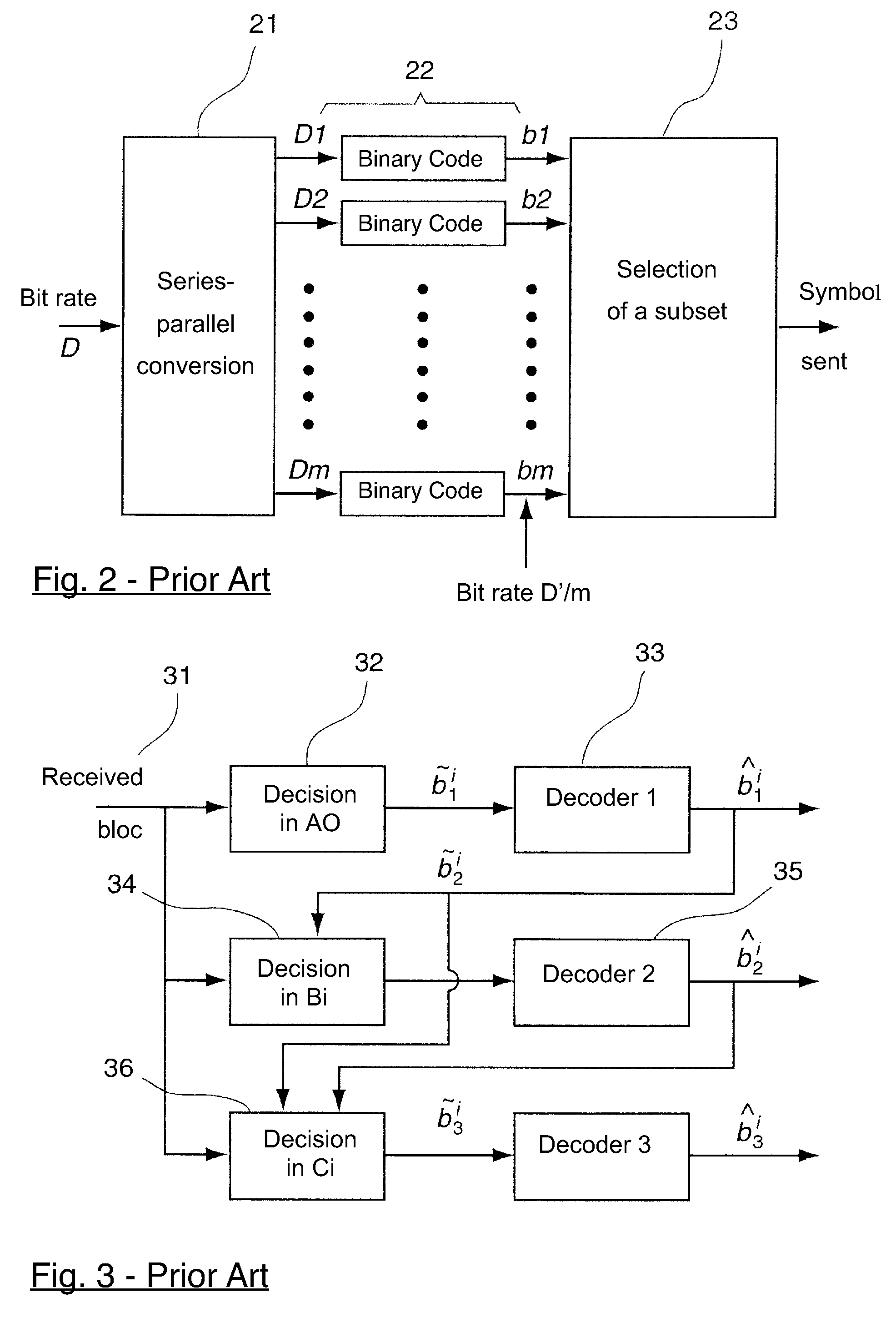
One drawback of this prior art technique therefore is that the decoding method conventionally implemented in the context of MLC coding shows mediocre performance.
In particular, such a technique of sub-optimal step-by-step decoding is poorly adapted to channels presenting additive Gaussian noise and Doppler-affected multiple-path channels.

Method used


Image

  • Reception of a signal modulated according to a multilevel coding technique
  • Reception of a signal modulated according to a multilevel coding technique
  • Reception of a signal modulated according to a multilevel coding technique

Examples


Embodiment Construction

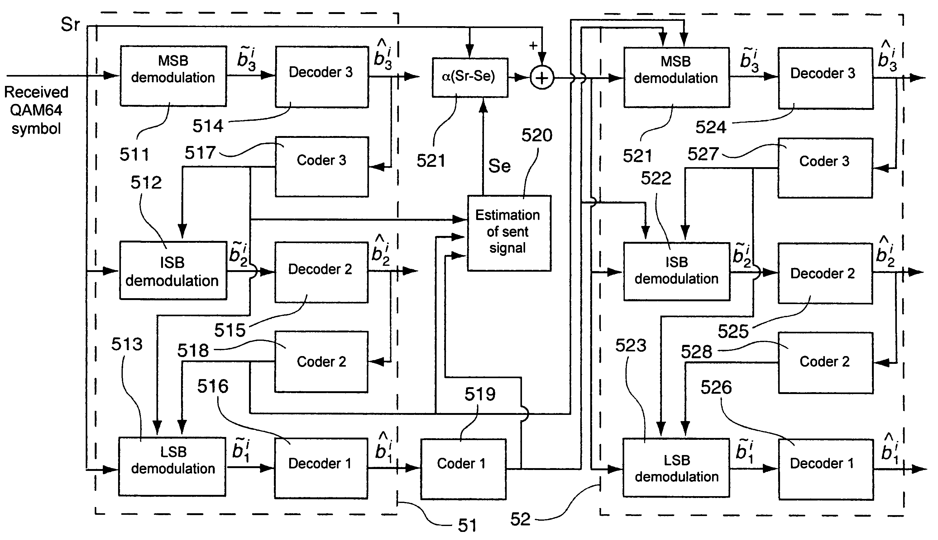
[0079]The general principle of the invention relies on taking account of the noise robustness of the different coding levels of a signal modulated according to a multi-level coding MLC technique, to determine the order of decoding of the received bits.

[0080]Referring to FIG. 4, we present the concept of robustness of an encoding level, in the context of a multi-level coding or MLC technique.

[0081]The robustness of a coding level may be illustrated by the curve of the binary error rate of this level, and the function of the signal-to-noise (S / N) ratio: throughout the document, a coding level shall be considered to be all the more robust as the binary error rate associated with it is low.

[0082]By decoding each coding level independently, i.e. without making any return loop from one level to another (in other words, the result of the decoding of one level is not used in the decoding of the next level)), it is possible to determine the level of noise robustness of each level. More parti...


PUM


Abstract

A method for receiving a signal modulated according to a multilevel coding technique, comprising at least two coding levels each having different noise robustness, said signal including a plurality of symbols each comprising at least one bit, assigned to one of said coding levels, said method comprising at least one decoding iteration including successive steps of decoding each of said received bits, at least one of said decoding steps integrated the result of at least one possible previous decoding step. The invention is characterized in that it consists in decoding said bits according to a predetermined sequence taking into account the robustness of said levels, the bit(s) assigned to the decoding level having the higher noise robustness, called most robust level, being decoded first.

Description

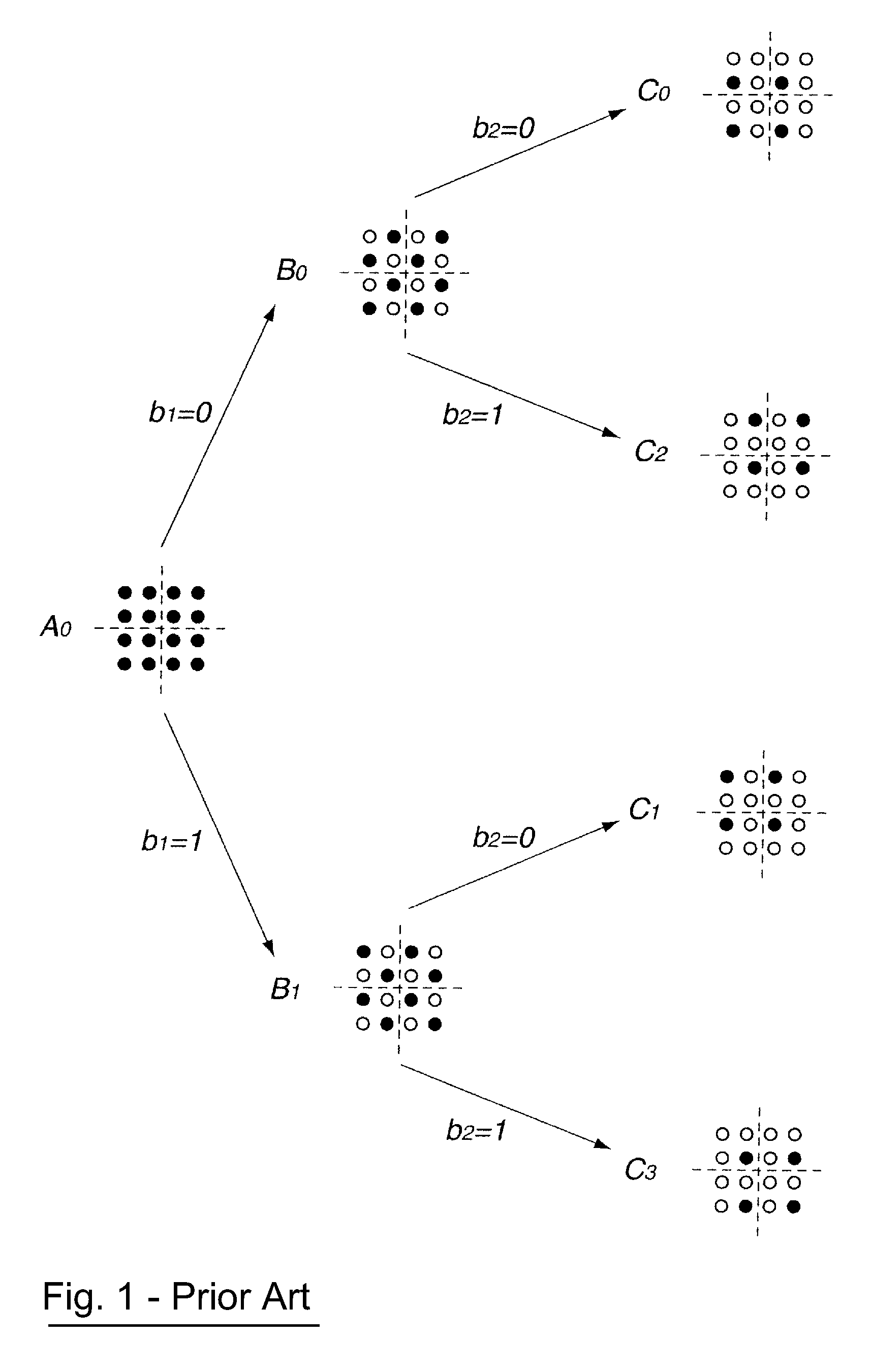
CROSS-REFERENCE TO RELATED APPLICATION[0001]This Application is a Section 371 National Stage Application of International Application No. PCT / FR2003 / 002878, filed Oct. 1, 2003 and published as WO 2004 / 032397 A1 on Apr. 15, 2004, not in English, which is based on French Application No. 02 / 12158, filed on Oct. 1, 2002, the contents of which is hereby incorporated by reference in its entirety.FIELD OF INVENTION[0002]The field of the invention is that of signal processing and digital communications.BACKGROUND OF THE INVENTION[0003]More specifically, the invention relates to a technique to optimize the decoding of a signal modulated according to a multi-level coding or MLC technique.[0004]To date, there are several known coded-modulation channel-coding techniques. Indeed, following Ungerboeck's discovery of lattice-coded modulation also known as MCT (“Channel Coding with Multilevel / Phase Signals”), described in IEEE Trans. IT, January 1982, 28, No. 1, pp. 55-67), block-coded modulation o...

Claims


Application Information

Patent Timeline
IPC IPC(8): H04L5/12H03M13/03H04L27/06H04L1/00H04L25/34
CPCH03M13/25H03M13/256H04L1/007H04L1/005H04L1/006
Inventor JAHAN, BRUNOLOUIN, PIERRICK
Owner TDF CORP
Learn More