
Engine autostop and autorestart control

a technology of engine and control, applied in the direction of machines/engines, propulsion parts, process and machine control, etc., can solve the problems of degraded control accuracy, degraded fuel injection control accuracy, and damage to various engine components, so as to improve fuel efficiency and reduce emissions

Active Publication Date: 2009-10-27
FORD GLOBAL TECH LLC
View PDF14 Cites 55 Cited by
  • Summary
  • Abstract
  • Description
  • Claims
  • Application Information

AI Technical Summary

Benefits of technology

[0001]Vehicles may use engines that automatically shut-down during idle or stopped vehicle conditions, also known as engine idle stop conditions, to improve fuel efficiency and reduce emissions.
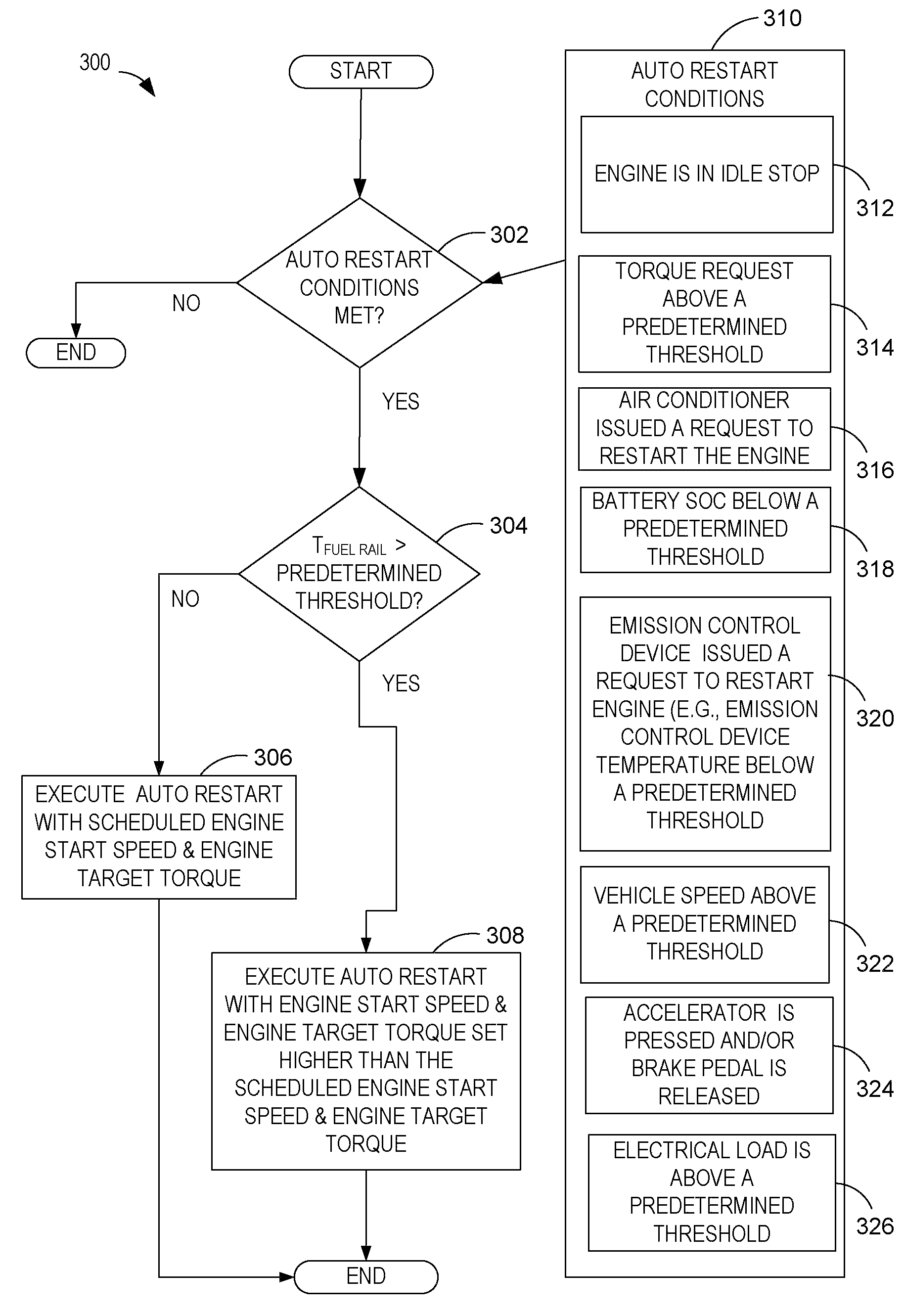
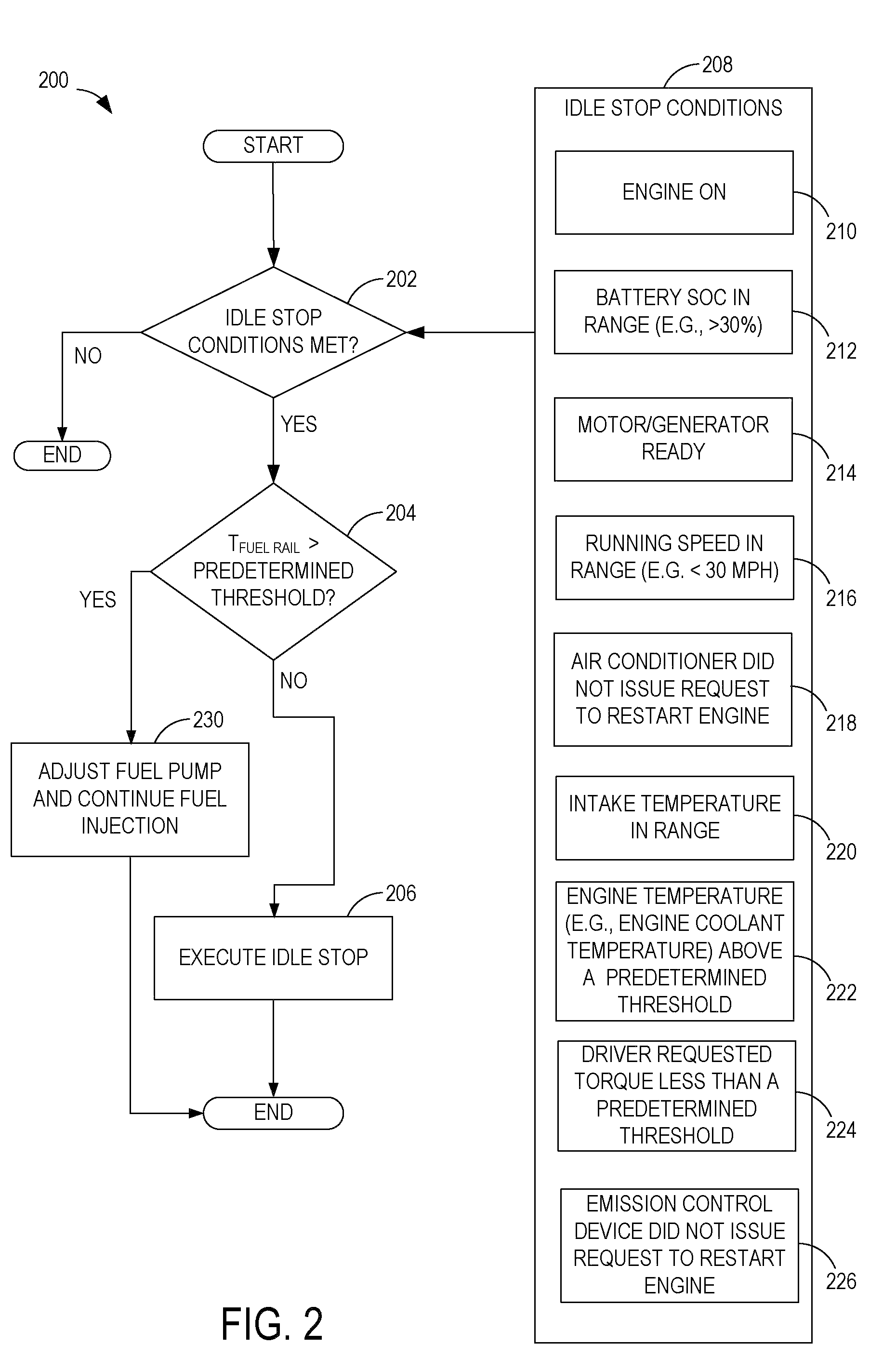
[0004]In one approach, at least some of the above issues may be addressed by a method of controlling engine operation of an engine that may be shut-down during engine idle stop conditions, the engine including a high pressure direct injection fuel system, the method comprising: during at least a first fuel rail temperature below a threshold, automatically stopping engine operation during a selected engine idle stop condition, without a driver requesting engine shut-down, and during at least a second fuel rail temperature above the threshold, maintaining engine operation during the selected engine idle stop condition. By considering fuel rail pressure effects when automatically stopping engine operation, it may be possible to avoid conditions that result in undesirably high fuel rail pressure during subsequent restarts. For example, by disabling the automatic stopping under such conditions, degraded operation may be reduced even when engine coolant temperatures are below temperatures that can result in component degradation.
[0005]Further, at least some of the above issues may be addressed by another aspect of the disclosed method wherein, during the second fuel rail temperature above the threshold, fuel injection is continued until a fuel rail pressure falls below a threshold, and then the engine operation is automatically stopped. In this way, it is possible to delay engine shut-down until fuel rail pressures can be sufficiently reduced. Consequently, upon the subsequent restart, adequate fueling control can be achieved. In one example, by stopping the fuel pump, pressure can be reduced through continued injection and engine operation / combustion, thereby sufficiently lowering the fuel pressure to enable the engine shut-down operation. In this way, even if the fuel pressure rises during the shutdown due to the fuel's high temperature, accurate fueling can be achieved during the subsequent restart.
[0006]At least some of the above issues may be addressed by still another aspect of the disclosed method including adjusting operation of a subsequent restart based on a previous fuel rail temperature of the high pressure fuel rail before the automatic stopping of the engine during selected engine idle stop conditions. In this way, even if fuel rail pressure rises during the shut-down to affect fuel injection control on the restart, due to the engine being operated at higher output torque for example, larger injection pulse widths of the injectors may enable sufficiently accurate injection control. In one example, the additional torque output may be further captured to regenerate a battery's state of charge.

Problems solved by technology

When the under-hood temperature, as indicated by the engine coolant temperature, is already high before the engine is shut-down, it may rise to a level as to potentially cause damage to various engine components during the engine shut-down.
However, the inventors herein have recognized various issues with the above approach.
Consequently, upon a subsequent engine start, fuel injection control accuracy may degrade due to the higher than desired fuel rail pressure combined with limits on the fuel injector dynamic range.
The degraded control accuracy may then lead to rough restarts, increased emissions, and / or engine misfire.
For example, by disabling the automatic stopping under such conditions, degraded operation may be reduced even when engine coolant temperatures are below temperatures that can result in component degradation.

Method used


Image

  • Engine autostop and autorestart control
  • Engine autostop and autorestart control
  • Engine autostop and autorestart control

Examples


Embodiment Construction

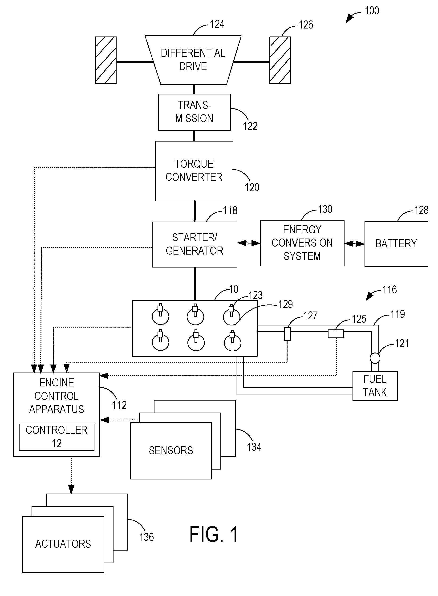
[0010]FIG. 1 is a diagram illustrating an example vehicle system 100 which utilizes an engine control apparatus 112 for controlling engine operation of an engine 10 that may be shut-down during engine idle stop conditions. The example vehicle system 100 is shown as a parallel hybrid electrical vehicle system and the engine 10 of the vehicle system 100 includes a high pressure direct fuel injection fuel system 116. It will be appreciated that in alternate embodiments of vehicle system 100, other engine and vehicle configurations may be possible, for example, the vehicle system may be a series hybrid electrical vehicle system, or a non-hybrid electrical vehicle system, such as a gasoline vehicle system or a diesel vehicle system.

[0011]In the example vehicle system 100 shown in FIG. 1, the driving force of the vehicle system may be generated by the engine 10 and / or an electric motor of the starter / generator 118 coupled to the engine 10. The driving force to the driving wheels 126 (e.g....


PUM


Abstract

Systems and methods are described for controlling engine operation of an engine that may be shut-down during engine idle stop conditions. The engine may include a high pressure direct injection fuel system. In one embodiment, a method comprises during at least a first fuel rail temperature below a threshold, automatically stopping engine operation during a selected engine idle stop condition; and during at least a second fuel rail temperature above the threshold, maintaining engine operation during the selected engine idle stop condition.

Description

BACKGROUND AND SUMMARY[0001]Vehicles may use engines that automatically shut-down during idle or stopped vehicle conditions, also known as engine idle stop conditions, to improve fuel efficiency and reduce emissions.[0002]One approach to managing automatic engine shut-down operation is provided by U.S. Pat. No. 6,817,329. In this example, an automatic engine shut-down operation is disabled responsive to high engine coolant temperatures. After engine shut-down, under-hood temperatures may continue to rise for a period of time before cooling to near ambient temperatures, since the cooling system is not in operation after engine shut-down. When the under-hood temperature, as indicated by the engine coolant temperature, is already high before the engine is shut-down, it may rise to a level as to potentially cause damage to various engine components during the engine shut-down. Thus, by disabling automatic engine shut-down responsive to high engine coolant temperatures, overheating of en...

Claims


Application Information

Patent Timeline
Patent Type & Authority Patents(United States)
IPC IPC(8): B60T7/12G05D1/00G06F17/00G06F7/00
CPCB60K6/365B60K6/547B60T1/10B60W10/06B60W10/08B60W30/18009B60W30/192F02D41/042F02D41/065F02D41/3836F02N11/0829B60K6/48Y02T10/48B60L2240/421B60L2240/423B60L2240/441B60L2240/445B60W20/00B60W2510/0604B60W2510/0638B60W2510/0676B60W2510/244B60W2520/10B60W2540/06B60W2540/10B60W2540/12B60W2560/04B60W2710/0616B60W2710/0644B60W2710/0666B60W2710/081B60W2710/083F02D41/3809F02D2200/0602F02D2200/0606Y02T10/6221Y02T10/6286B60W2530/211Y02T10/40Y02T10/62B60W30/194
Inventor BOESCH, MATHEW ALAN
Owner FORD GLOBAL TECH LLC
Learn More