
Machine for packing stacks of disc-shaped articles inside rigid cylindrical containers

a technology of disc-shaped objects and cylindrical containers, which is applied in the direction of packaging goods, liquid handling, and closure using stoppers, etc., can solve the problems of increasing the number of complications, the time required for these operations is inferior to the time required, and the speed of the machine is extremely slow, so as to achieve the greatest simplicity of construction and high productivity.

Active Publication Date: 2009-11-03
MARCHESINI GROUP SPA
View PDF15 Cites 10 Cited by
  • Summary
  • Abstract
  • Description
  • Claims
  • Application Information

AI Technical Summary

Benefits of technology

[0012]An aim of this invention is to obviate the abovementioned drawbacks by providing a machine for packing stacks of disc-shaped articles, tablets in particular, inside rigid cylindrical containers, tubes in particular, which adapts the advancement cycle of the containers to the optimum conditions for each operating station of the machine, in such a way as to ensure high productivity while at the same time achieving the greatest simplicity of construction for the operating organs situated at each station.
[0013]A further aim of the invention is to provide a machine which has a limited cost and is particularly reliable and versatile under all operating conditions.
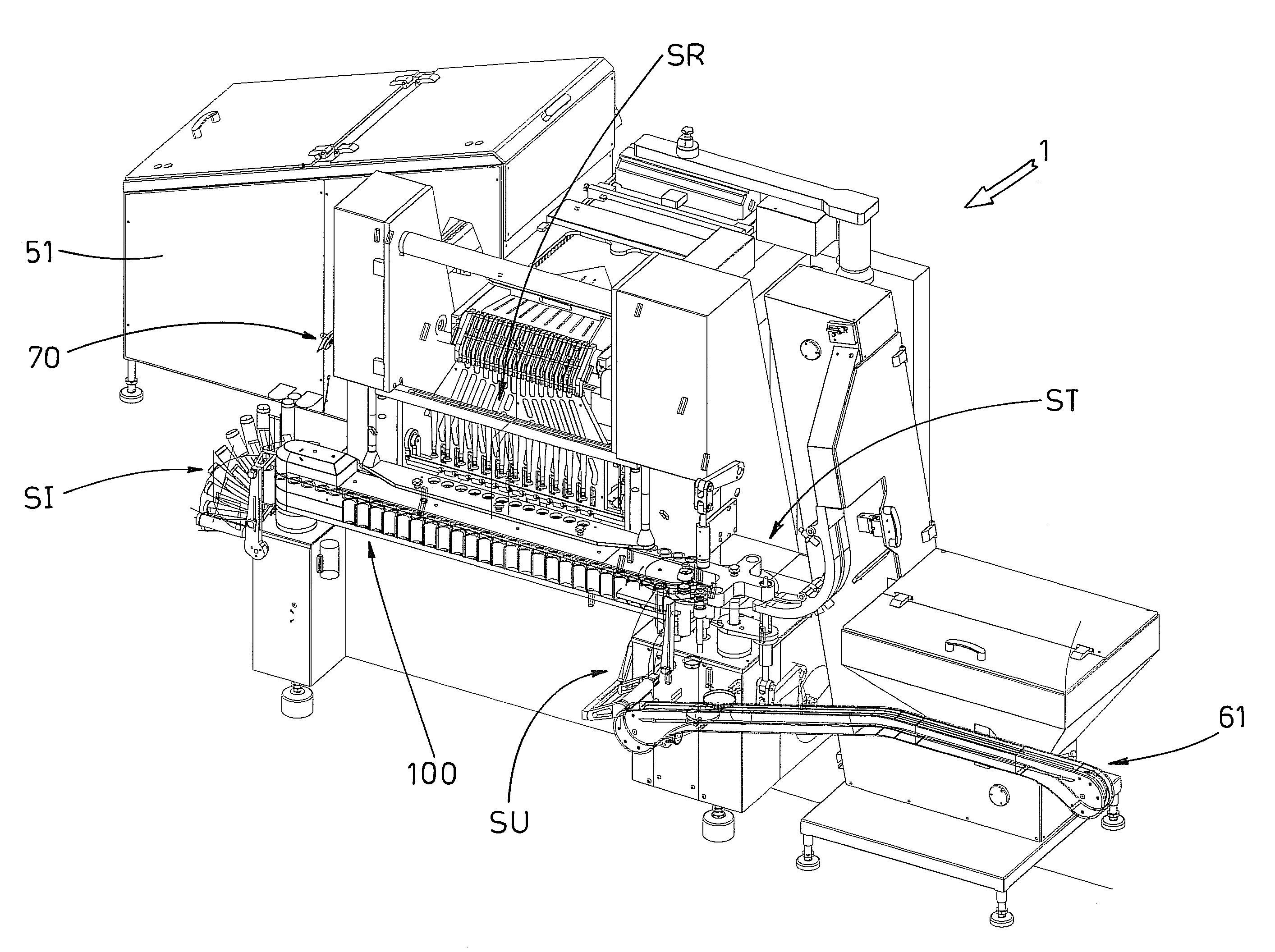
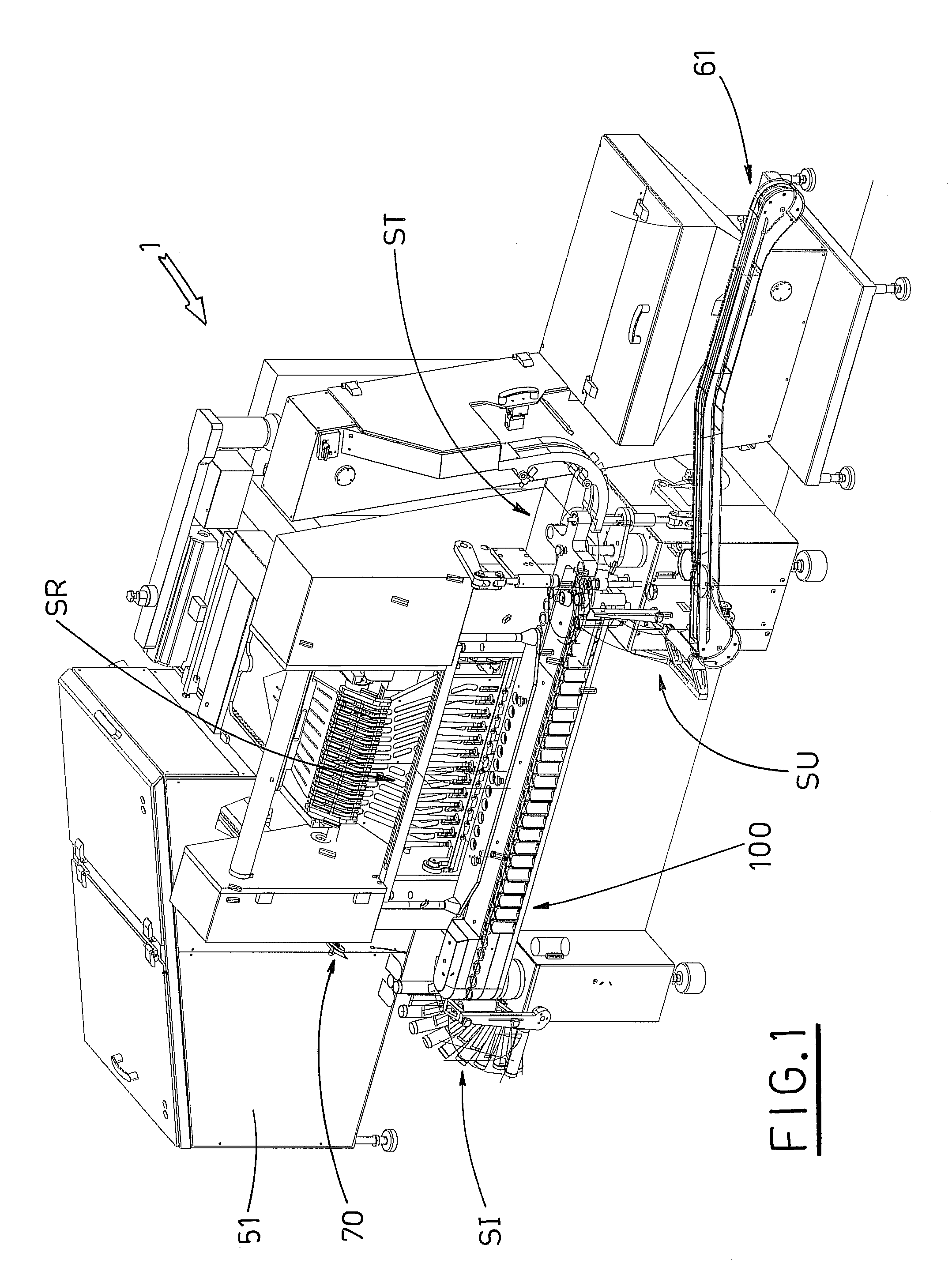
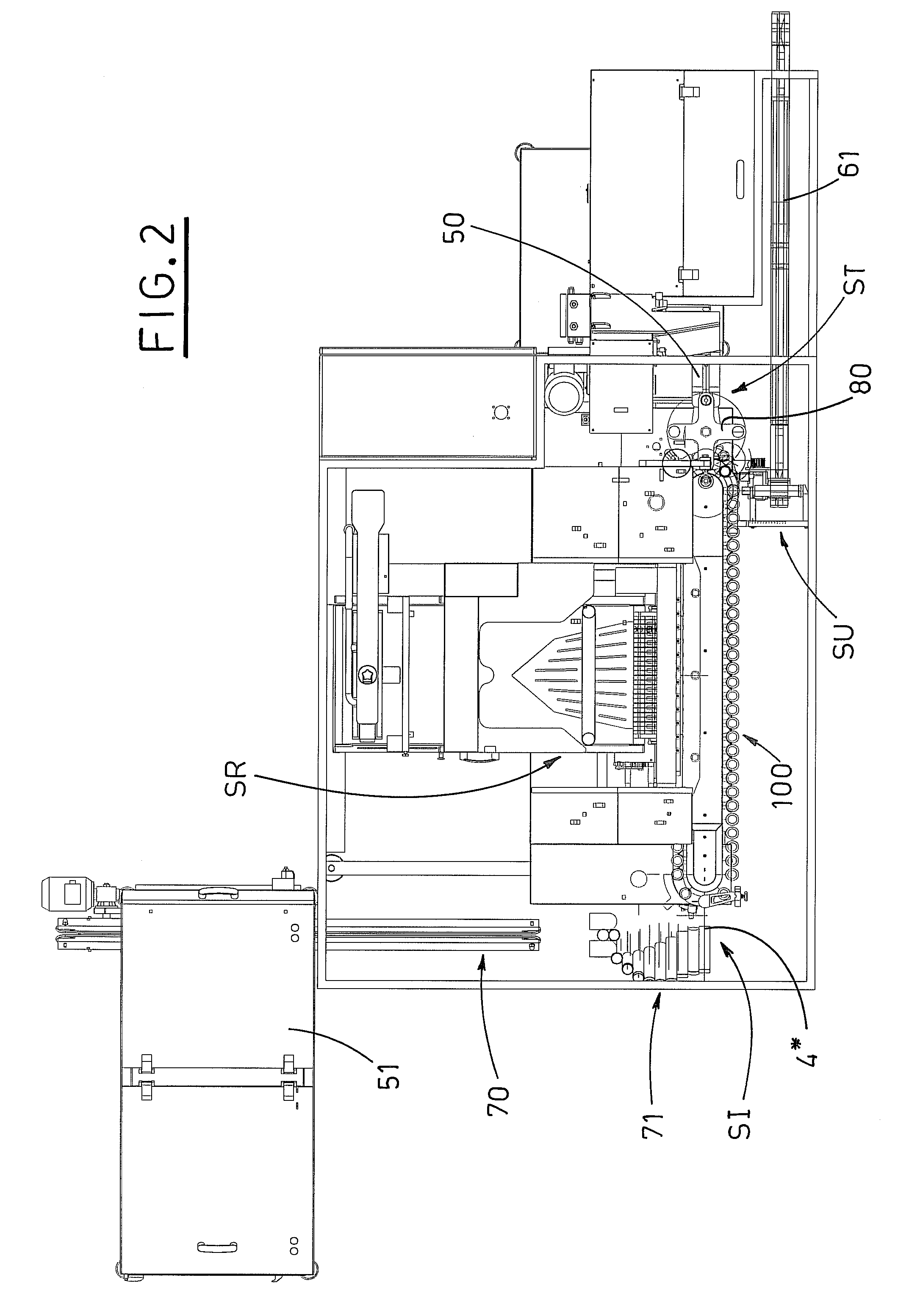
[0015]The above-mentioned aims are achieved by means of a machine for packing stacks of disc-shaped articles in rigid cylindrical containers, wherein it comprises: a line which supplies empty cylindrical containers to an inlet station containing organs which release the empty containers, arranged with axes vertical and with mouths facing upwards, to corresponding gripping organs provided on a multiple conveyor; a filling station, provided downstream of the inlet station, which contains a plurality of supply units which release a predetermined quantity of stacked disc-shaped articles into a plurality of cylindrical containers in a paused state, which plurality of cylindrical containers are borne by the multiple conveyor; a closing station, located downstream of the filling station, containing means which pick up caps coming from a supply line and insert the caps into the mouths of the filled containers borne by the multiple conveyor, thus closing the containers; an outlet station, provided downstream of the closing station, containing second organs which pick up paused individual closed containers borne by the multiple conveyor and release the containers to transporter organs; and further wherein the multiple conveyor comprises: at least an upper transporter and a lower transporter, which extend one above the other along a same ring-wound trajectory, to each of which at least two batteries of gripping organs are associated, at a same distance from one another, the at least two batteries associated to the upper transporter being intercalated with the corresponding at least two batteries associated to the lower transporter, defining a number of empty places between the at least two consecutive batteries of the upper transporter and of the lower transporter, which number of empty places is dynamically variable from zero to a maximum value; motor organs which independently activate the upper transporter and the lower transporter, resulting in an uninterrupted and intermittent presence of gripping organs at the inlet station, and of gripping organs associated to a relative container at the closing station and the outlet station and resulting in keeping the battery situated immediately downstream of the inlet station paused in the filling station, such as to avoid interference between the containers paused in the filling station and the empty containers associated to the gripping organs situated upstream of the filling station, which empty containers are intermittently-activated.

Problems solved by technology

The other operations, performed in the stations upstream and downstream of the filling station, are carried out to coincide with the rest stage for the filling operation, even though the times required for these operations are inferior to the time required for filling.
A technical solution of this kind provides an extremely slow machine with unsatisfactory productivity.
In this way, a proportional increase in productivity is obtained in comparison with the first type of machine, with the same duration of the rest stage, but considerable constructional complications arise concerning the machine's operating organs: the greater the number of containers to be dealt with simultaneously, the more numerous these complications become.
A machine of this type provides reasonable, but not optimum productivity compared with market standards, and presents significant negative aspects both in terms of costs and operational reliability.

Method used


Image

  • Machine for packing stacks of disc-shaped articles inside rigid cylindrical containers
  • Machine for packing stacks of disc-shaped articles inside rigid cylindrical containers
  • Machine for packing stacks of disc-shaped articles inside rigid cylindrical containers

Examples


Embodiment Construction

[0029]In the tables the reference number 1 indicates the machine of the invention for packing stacks of disc-shaped articles 2, tablets in particular, inside rigid cylindrical containers 4, for example tubes, comprising:[0030]a supply line 70 supplying empty cylindrical tubes 4 arranged with vertical axes and with mouths 4a facing upwards;[0031]an inlet station SI, situated downstream of the supply line 70, in which deflector organs 71 operate which enable the cylindrical containers 4 to be tilted sideways so that the axes thereof are preferably horizontally oriented, and first organs 72, which pick up individual containers 4 tipped on their side and release them, with the axes thereof vertical and mouths 4a facing upwards, to corresponding gripping organs 3 provided by a multiple conveyor 100;[0032]downstream of the inlet station SI, a filling station SR in which a plurality of supply units 90 operate, releasing a predetermined quantity of tablets 2, stacked one upon the other, int...


PUM

PropertyMeasurementUnit
distanceaaaaaaaaaa
elasticaaaaaaaaaa
shapeaaaaaaaaaa

Abstract

A machine for packing tablets inside rigid tubes exhibits: a supply line for supplying empty tubes arranged with vertical axes and mouths facing upwards; an inlet station wherein deflector organs operate which tip the cylindrical containers on sides thereof, and first organs which pick up individual thus-tipped containers and release the containers to corresponding gripping organs provided by a multiple conveyor; a filling station in which a plurality of supply units release a predetermined quantity of tablets, stacked one on the other, into paused tubes, borne by the multiple conveyor; a closing station containing devices which insert caps into the mouths of the filled containers borne by the multiple conveyor; an outlet station containing devices which pick up paused individual closed containers borne by the multiple conveyor and release the containers onto transporter organs.

Description

BACKGROUND OF THE INVENTION[0001]The invention concerns the technical sector of machines for packing articles, with particular reference to machines for packing stacks of disc-shaped articles, in particular tablets, in rigid cylindrical containers, especially tubes.[0002]The prior art includes machines for filling and subsequently capping vertically arranged, rigid cylindrical containers of a tubular shape.[0003]In these machines, containers coming from a supply line are loaded one by one onto a conveyor to be transferred firstly to a filling station and then, possibly through other intermediate stations, to a capping station, and finally to an outlet station.[0004]At the filling station, a plurality of articles are inserted into the tubular containers, one-by-one and stacked one on the other.[0005]This filling operation must necessarily be performed with the container at rest, the duration of the operation depending on the time required for a single insertion and on the number of i...

Claims


Application Information

Patent Timeline
Patent Type & Authority Patents(United States)
IPC IPC(8): B65B57/00B65B43/46B65B7/28B65B43/54B65B5/10
CPCB65B5/103B65B43/54B65B43/46B65B7/2821
Inventor MONTI, GIUSEPPE
Owner MARCHESINI GROUP SPA
Learn More