
Optical element for condensing incident light

an incident light and optical element technology, applied in the field of optical elements, can solve the problems of inability to detect the position of the minute structure, and the space where the photodiodes are formed around the minute structure, and achieve the effect of accurate detection of the position

Inactive Publication Date: 2009-11-03
KONICA MINOLTA OPTO
View PDF26 Cites 7 Cited by
  • Summary
  • Abstract
  • Description
  • Claims
  • Application Information

AI Technical Summary

Benefits of technology

"The present invention provides an optical element that can accurately detect the positions of minute structures on a metallic thin film. This is achieved by forming a plurality of near-field light generating minute structures and a position detecting minute structure that detects the positions of the near-field light generating minute structures. The optical element can easily match the optical spot with the near-field light generating minute structures and the position detecting minute structures. The near-field light generating minute structures can be created simultaneously with the metallic thin film, making it easy to accurately detect their positions. The minute structures can generate plasmon resonance, enabling efficient optical recording / reproduction. The optical element can be easily adjusted to the position of the condensing spot. The position detecting minute structures can be easily found, and the relative position relationship between them can be easily understood. The near-field light generating minute structures can be located to the optical spot easily."

Problems solved by technology

In the adjusting method disclosed in Japanese Patent Application Laid-Open No. 2000-293877, a plurality of photodiodes are formed around the minute structure, but since the minute structures have size of not more than 1 μm and the gap therebetween is not more than 2 μm, there is a problem that no a space where the photodiodes are formed around the minute structures.
Further, in the adjusting method disclosed in Japanese Patent Application Laid-Open No. 2002-236087, when a plurality of minute structures are formed on the metallic thin film which is formed uniformly, the intensity of the reflected light is hardly different between the thin film portion and the minute structures, and thus there is a problem that the positions of the minute structures cannot be actually detected.

Method used


Image

  • Optical element for condensing incident light
  • Optical element for condensing incident light
  • Optical element for condensing incident light

Examples


Embodiment Construction

[0031]An optical element and an optical spot position adjusting method according to the present invention are explained below with reference to the drawings, but the present invention is not limited to embodiments.

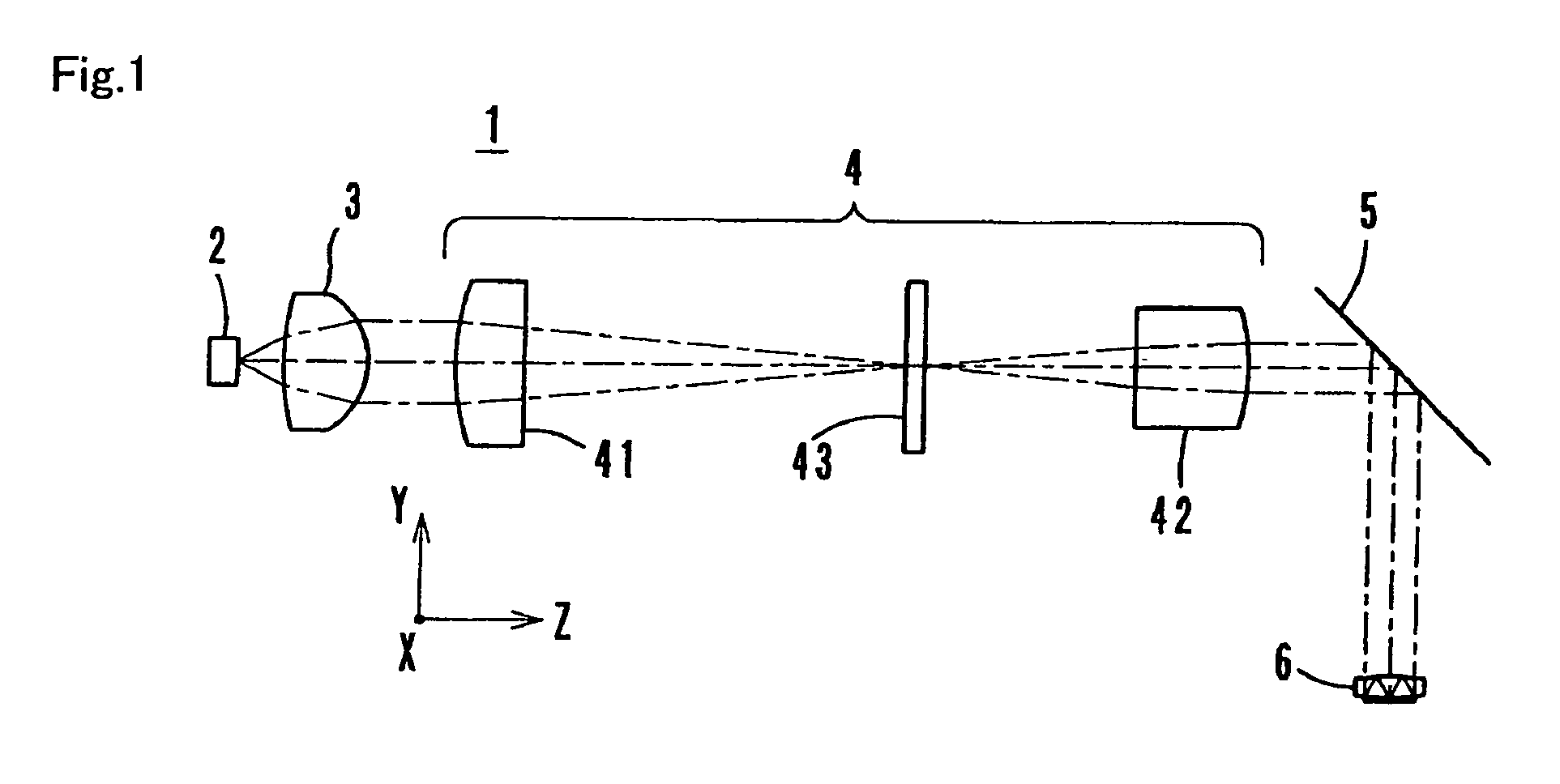
[0032]An optical device for optical recording having the optical element according to the present invention is explained. The optical device for optical recording 1 is, as shown in FIG. 1, composed of a laser diode 2 as a light source, a collimating lens 3, a beam diameter converting optical system 4, a plane mirror 5 and a condensing element 6 as an optical element for generating near-field light.

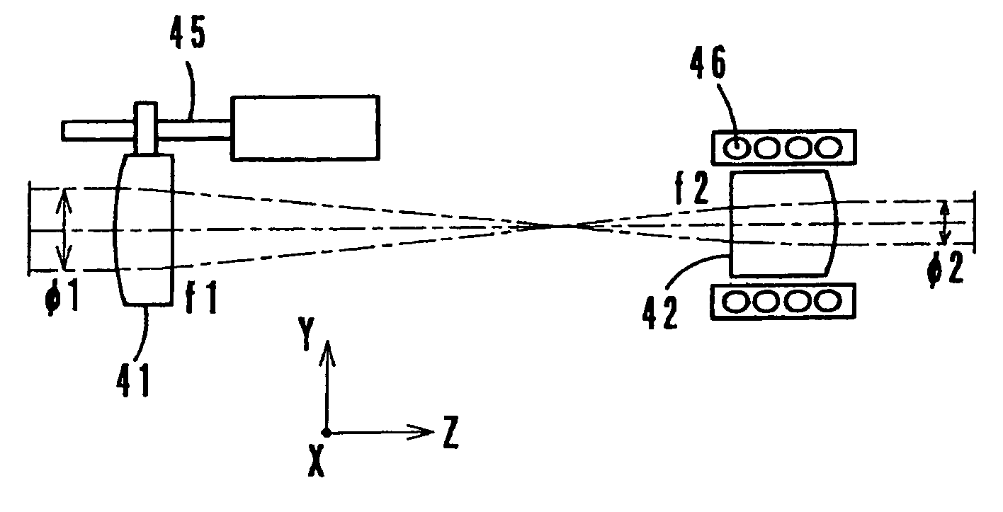
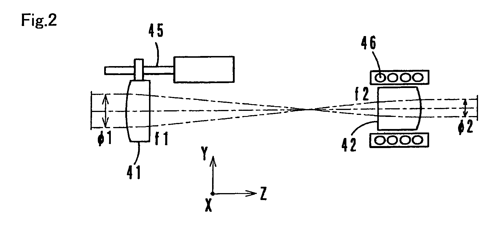
[0033]The laser diode 2 radiates divergent light with predetermined wavelength to an optically axial direction Z. The collimating lens 3 converts diffuse light radiated from the laser diode 2 into approximately parallel light. The beam diameter converting optical system 4 is composed of a first lens 41 as a convex lens, a second lens 42 as a convex lens and a diaphragm 43, and it...


PUM


Abstract

To obtain an optical element for generating near-field light which can accurately detect positions of a plurality of minute structures formed on a metallic thin film provided to a condensing surface, and a method of adjusting an optical spot position of the optical element. The metallic thin film is formed on the condensing surface of the optical element that condenses incident light so as to generate near-field light smaller than an condensing spot B near a condensing point, and a plurality of openings (minute structure) for generating the near-field light are formed into a matrix matter on the metallic thin film, and position detecting structures are formed on positions that partitions the openings is formed. Scanning in X and Y directions is carried out by a light beam, and its reflected light is detected so that the positions of the openings are detected.

Description

[0001]The present application claims priority to Japanese Patent Application No. 2004-290705 filed on Oct. 1, 2004, the entire contents of which are hereby incorporated by reference.BACKGROUND OF THE INVENTION[0002]1. Field of the Invention[0003]The present invention relates to an optical element that creates a minute optical spot using a minute structure and an optical spot position adjusting method. Specifically, the invention relates to the optical element that is used for recording and / or reproducing information using near-field light, and the optical spot position adjusting method in the optical element.[0004]2. Description of the Related Art[0005]In recent years, in optical recording and reproducing techniques, the use of a near-field light generating structure is variously proposed in order to obtain a minute optical spot. In order to realize the recording / reproduction using near-field light, a solid immersion lens or a solid immersion mirror is used as a condensing element, ...

Claims


Application Information

Patent Timeline
Patent Type & Authority Patents(United States)
IPC IPC(8): H01J3/14H01J5/16
CPCG11B7/1387G11B7/1374G11B7/08505Y10S977/862
Inventor OKITSU, MASAHIROOGURA, KAZUYUKIKONNO, KENJIHATANO, HIROSHI
Owner KONICA MINOLTA OPTO
Features
  • Generate Ideas
  • Intellectual Property
  • Life Sciences
  • Materials
  • Tech Scout
  • Unparalleled Data Quality
  • Higher Quality Content
  • 60% Fewer Hallucinations
Learn More