Resonant gate drive circuits

a gate drive and circuit technology, applied in the direction of power conversion systems, diodes, pulse techniques, etc., can solve the problems of gate driving loss, gate drive loss increase, and penalty on the overall converter efficiency become significant, so as to reduce the loss of gate driving and conduction loss

Active Publication Date: 2009-11-03
GANPOWER INT INC
View PDF19 Cites 53 Cited by
  • Summary
  • Abstract
  • Description
  • Claims
  • Application Information

AI Technical Summary

Benefits of technology

[0009]One object of the invention is to provide a resonant gate drive system to reduce the gate drive loss and other losses for power switching devices having an input capacitor.
[0010]Another object of the invention is to provide one resonant gate drive circuit that can drive two separate power switching devices with symmetrical signals to reduce the gate drive loss and conduction loss for the power switching devices.
[0011]Another object of the invention is to provide one resonant gate drive circuit that can drive two separate power switching devices with complimentary signal to reduce the gate drive loss and conduction loss for the power switching devices.
[0012]Another object of the invention is to provide one resonant gate drive circuit that can drive one low side and one high side power switching devices with complimentary or symmetrical signal to reduce gate drive loss, switching loss and conduction loss.BRIEF STATEMENT OF INVENTION
[0018]so as to recover the energy loss for charging and discharging the gate capacitor of the power switching devices and to reduce the switching loss of the power switching device.

Problems solved by technology

The development of microprocessor and other integrated circuits introduces new challenges to the development of power converters.
At low power levels the resulting penalty on the overall converter efficiency become significant.
Therefore, in low voltage, high current applications, the gate driving loss will also increase when the low on-resistance MOSFETs are chosen to reduce the conduction loss.
37-43, proposed by J. Diaz, M. A. Perez, F. M. Linera, F. Aldana, which makes the gate driver too complicated and the energy that can be recovered is also limited.
All the above solutions can only recover limited gate driving loss and have no other benefits.
180-186, but the required control signals are difficult to generate, and the coupled inductor is expensive and hard to design.
di / dt is another serious issue if the switching frequency is to be increased.

Method used


Image

  • Resonant gate drive circuits
  • Resonant gate drive circuits
  • Resonant gate drive circuits

Examples


Embodiment Construction

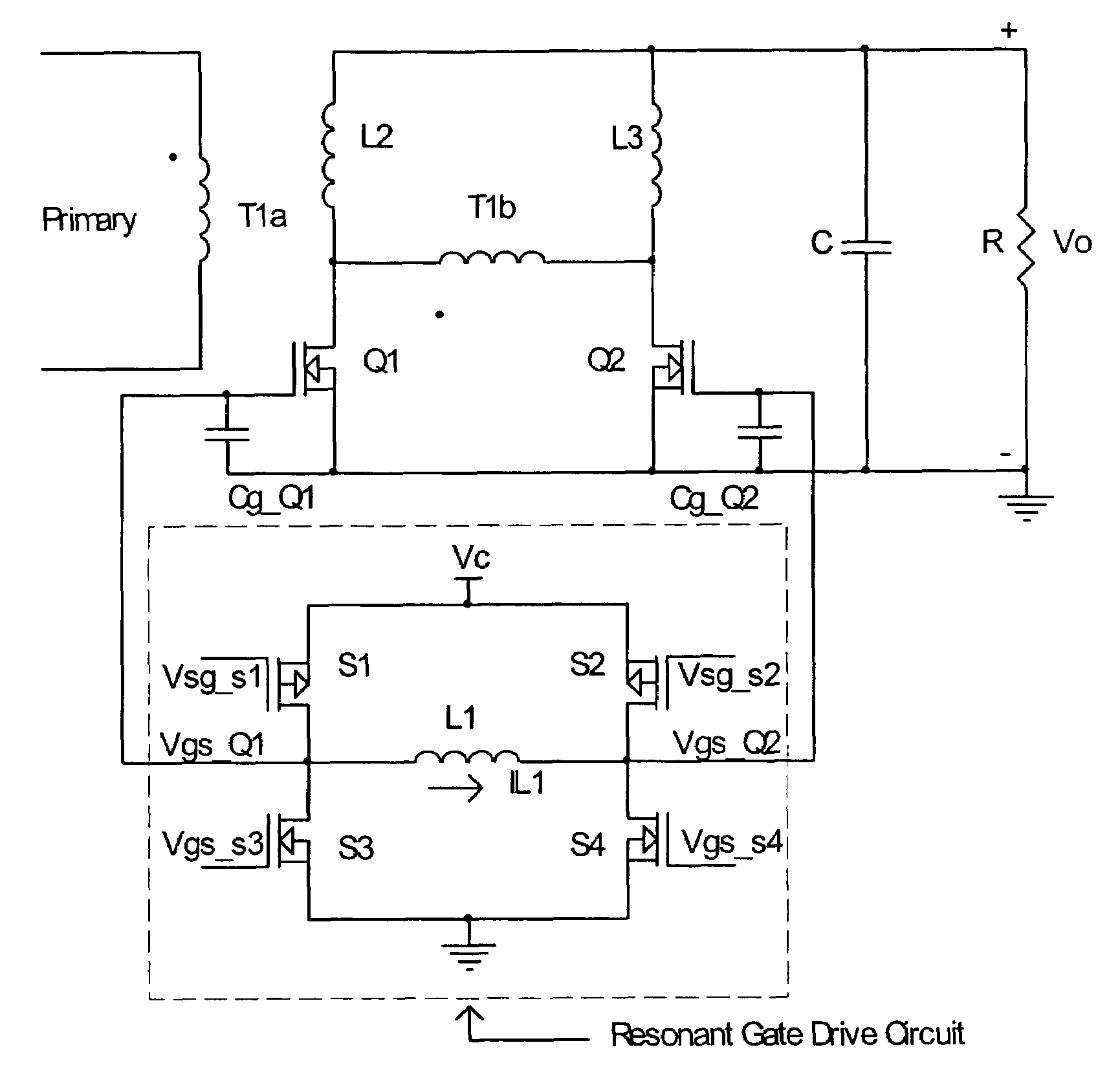
[0041]This invention proposes a new resonant gate drive scheme that can control a power switching device having a gate capacitor, such as a MOSFET (Metal Oxide Semiconductor Field Effect Transistor), IGBT (Gate Insulate Bipolar Transistor), or MCT (MOS Controlled Thyristor), etc. For ease of description of this specification, MOSFET will be used as a non-limiting example for all such devices.

[0042]As compared with the conventional resonant gate drive scheme, the proposed resonant gate drive scheme can control two separate power switching devices. It can reduce not only the gate drive loss. It can also reduce the switching loss of these power switching devices.

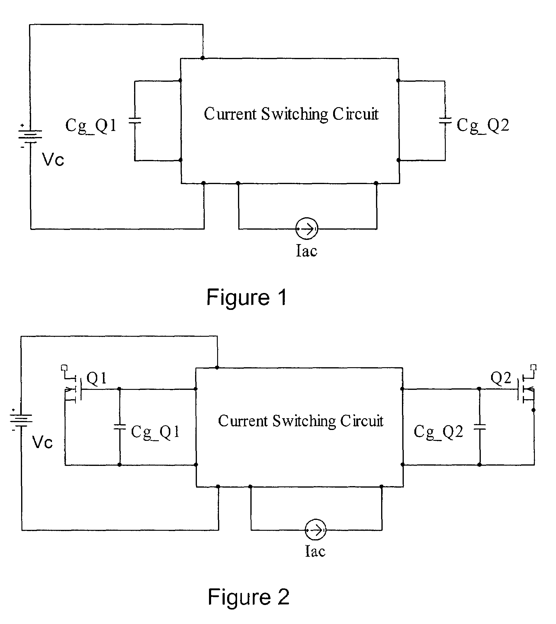
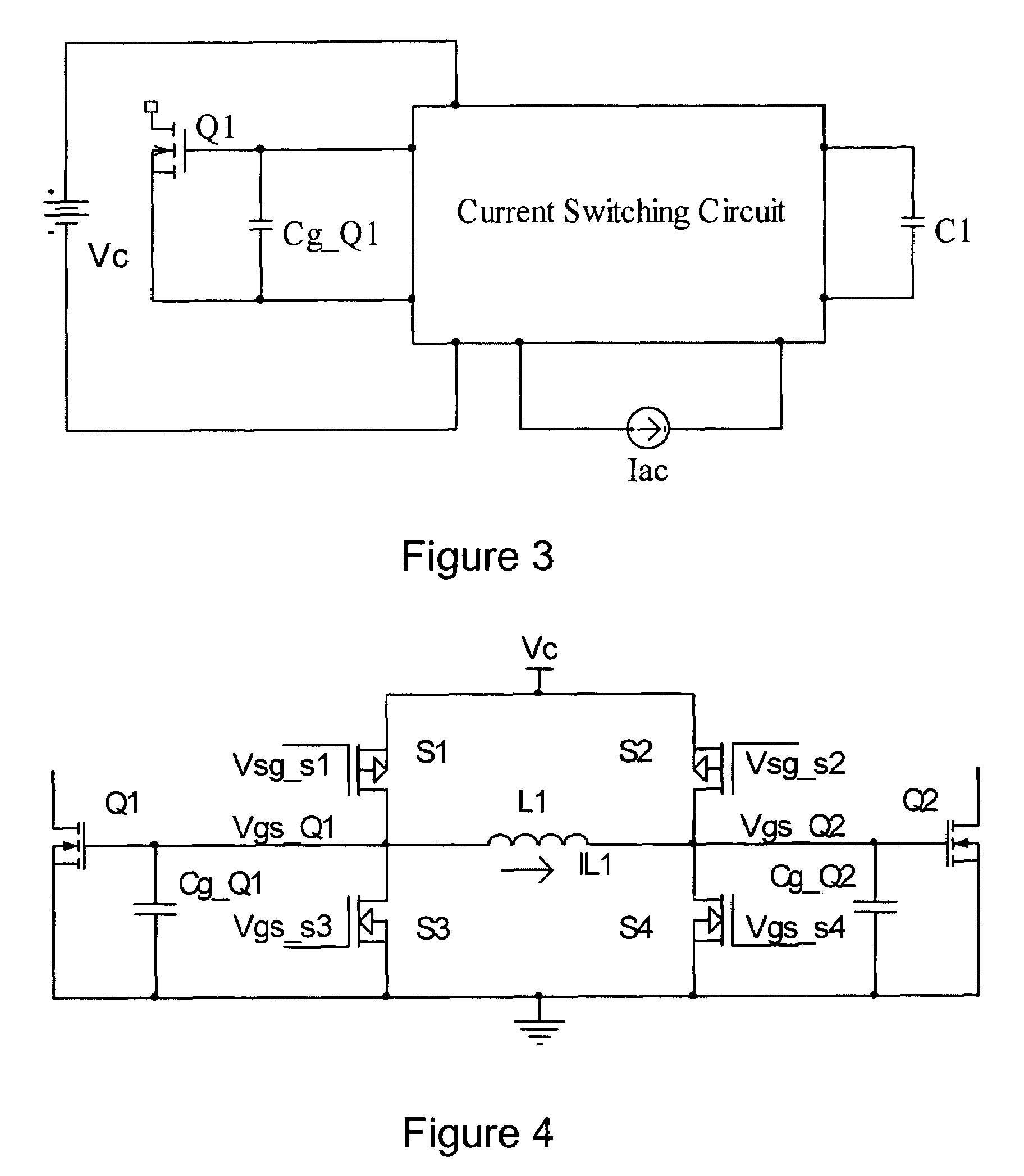
[0043]The circuit block diagram of the proposed scheme is shown in FIG. 1. In the figure, Cg_Q1, Cg_Q2 are capacitors that will be charged and discharged. Vc is a voltage source. Iac is an alternating current source. For half the switching period, its value is positive and for the other half of the switching period, its value i...


PUM


Abstract

A resonate gate drive circuit for driving at least one power switching devices recovers energy loss for charging and discharging the input capacitance of the power switching devices. The gate drive circuit charging and discharging the gate capacitor with a high level current, so the switching loss of the power switching devices can also be reduced. The gate drive circuit can clamp and keep the voltage across the gate capacitor to a certain level while the power switching devices turn on, and it can also clamp and keep the voltage across the gate capacitor to almost zero while the power switching devices turn off. The gate drive circuit comprises four small semiconductor bidirectional conducting switching devices connected in full-bridge configuration. An inductor is connected to the two junctions of the full-bridge configuration to help switching the current direction. A capacitor in series with the inductor is necessary for some applications. A bootstrap circuit, which is widely used in conventional gate drive circuitry, is also necessary for this resonant gate drive circuit when it is adopted for high-side and low-side applications.

Description

FIELD OF INVENTION[0001]This invention relates to DC-DC and AC-DC switching converters. More particularly, it relates to an effective way to turn on and to turn off the MOSFET that is used in such converters.BACKGROUND OF INVENTION AND PRIOR ART[0002]The development of microprocessor and other integrated circuits introduces new challenges to the development of power converters. In order to reduce the passive component size, and also to meet the stringent transient response requirement, the switching frequency of the power converter will move into the MHz range in the next few years.[0003]At high frequency and low power application, the effect of the gate-driver on the overall converter becomes more significant. As the operating frequency of power converters is raised, the losses associated with driving the power MOSFET rise, which is proportional to the switching frequency. At low power levels the resulting penalty on the overall converter efficiency become significant. On the other...

Claims


Application Information

Patent Timeline
Patent Type & Authority Patents(United States)
IPC IPC(8): H03K17/74
CPCH02M1/08H03K17/04163H03K17/04123
Inventor YANG, ZHIHUALIU, YAN-FEI
Owner GANPOWER INT INC
Why Eureka
Try Eureka