Resonant gate drive circuits
a gate drive and circuit technology, applied in the direction of power conversion systems, diodes, pulse techniques, etc., can solve the problems of gate driving loss, gate drive loss increase, and penalty on the overall converter efficiency become significant, so as to reduce the loss of gate driving and conduction loss
- Summary
- Abstract
- Description
- Claims
- Application Information
AI Technical Summary
Benefits of technology
Problems solved by technology
Method used
Image
Examples
Embodiment Construction
[0041] This invention proposes a new resonant gate drive scheme that can control a power switching device having a gate capacitor, such as a MOSFET (Metal Oxide Semiconductor Field Effect Transistor), IGBT (Gate Insulate Bipolar Transistor), or MCT (MOS Controlled Thyristor), etc. For ease of description of this specification, MOSFET will be used as a non-limiting example for all such devices.
[0042] As compared with the conventional resonant gate drive scheme, the proposed resonant gate drive scheme can control two separate power switching devices. It can reduce not only the gate drive loss. It can also reduce the switching loss of these power switching devices.
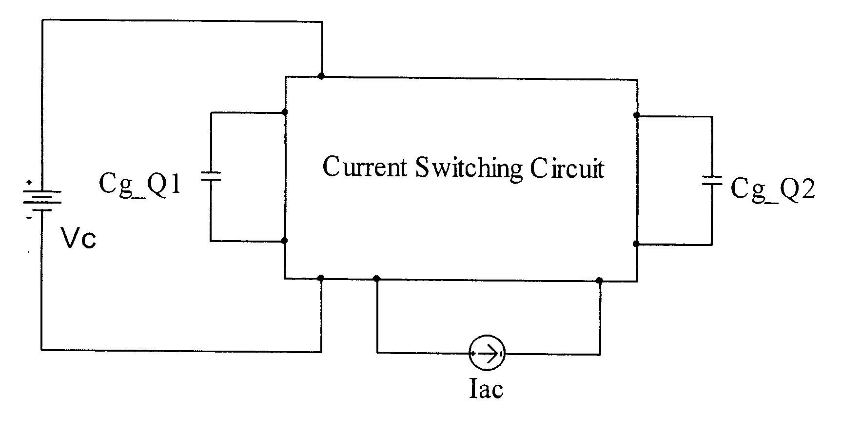
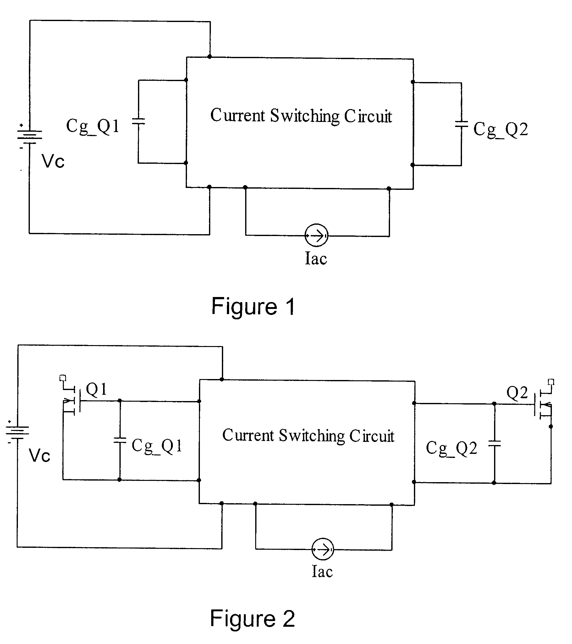
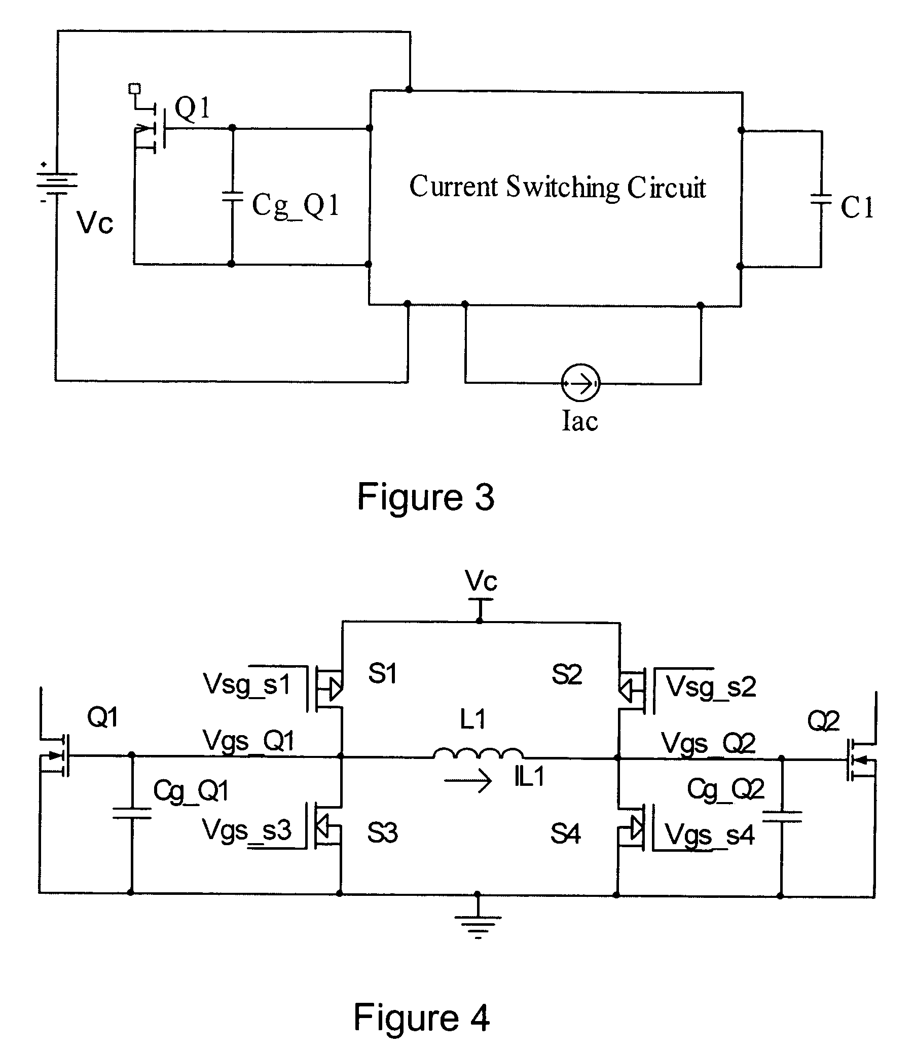
[0043] The circuit block diagram of the proposed scheme is shown in FIG. 1. In the figure, Cg_Q1, Cg_Q2 are capacitors that will be charged and discharged. Vc is a voltage source. Iac is an alternating current source. For half the switching period, its value is positive and for the other half of the switching period, its va...
PUM
 Abstract
Description
Claims
Application Information
 - R&D
- Intellectual Property
- Life Sciences
- Materials
- Tech Scout
- Unparalleled Data Quality
- Higher Quality Content
- 60% Fewer Hallucinations
Browse by: Latest US Patents, China's latest patents, Technical Efficacy Thesaurus, Application Domain, Technology Topic, Popular Technical Reports.
© 2025 PatSnap. All rights reserved.Legal|Privacy policy|Modern Slavery Act Transparency Statement|Sitemap|About US| Contact US: help@patsnap.com


