Methods and systems of variable extraction for gas turbine control

a gas turbine and variable extraction technology, applied in the direction of engine control, machine/engine, mechanical equipment, etc., can solve the problems of increased emissions, extensive damage to the turbine, damage to the turbine components, etc., and achieve the effect of reducing the amount of compressed air extracted from the turbine compressor

Inactive Publication Date: 2009-11-17
GENERAL ELECTRIC CO
View PDF12 Cites 21 Cited by
  • Summary
  • Abstract
  • Description
  • Claims
  • Application Information

AI Technical Summary

Problems solved by technology

Exceeding these temperatures may cause damage to turbine components or cause increased emissions levels.
Exceeding this limitation may cause the unit to surge, which may cause extensive damage to the turbine.
Exceeding this maximum flow rate may damage turbine components.
Because some of the compressor flow is recycled to the inlet, this method reduces the amount of flow through the compressor that expands through the turbine, which reduces the output of the turbine.
Although this approach may be used to allow the gas turbine unit to operate at a maximum level loaded across changing ambient conditions (while respecting operational boundaries), it comes with a cost, as it reduces the thermal efficiency of the gas turbine.
Closing the inlet guide vanes may restrict the passage of air to the compressor and, thus, decreases the amount of air entering the compressor.
This approach also may be used to allow the gas turbine unit to operate at a maximum level load across changing ambient conditions (while respecting operational boundaries), but it also reduces the thermal efficiency of the gas turbine by operating the compressor away from its optimum design point.
However, as is known in the art, the reduction in combustion temperature decreases the efficiency of the gas turbine engine.
These known control methods thus adversely affect the efficiency of the gas turbine engine.
Further, none of these control methods take advantage of the specific components that are part of an IGCC power generation system to allow the system to operate more efficiently.

Method used


Image

  • Methods and systems of variable extraction for gas turbine control
  • Methods and systems of variable extraction for gas turbine control
  • Methods and systems of variable extraction for gas turbine control

Examples


Embodiment Construction

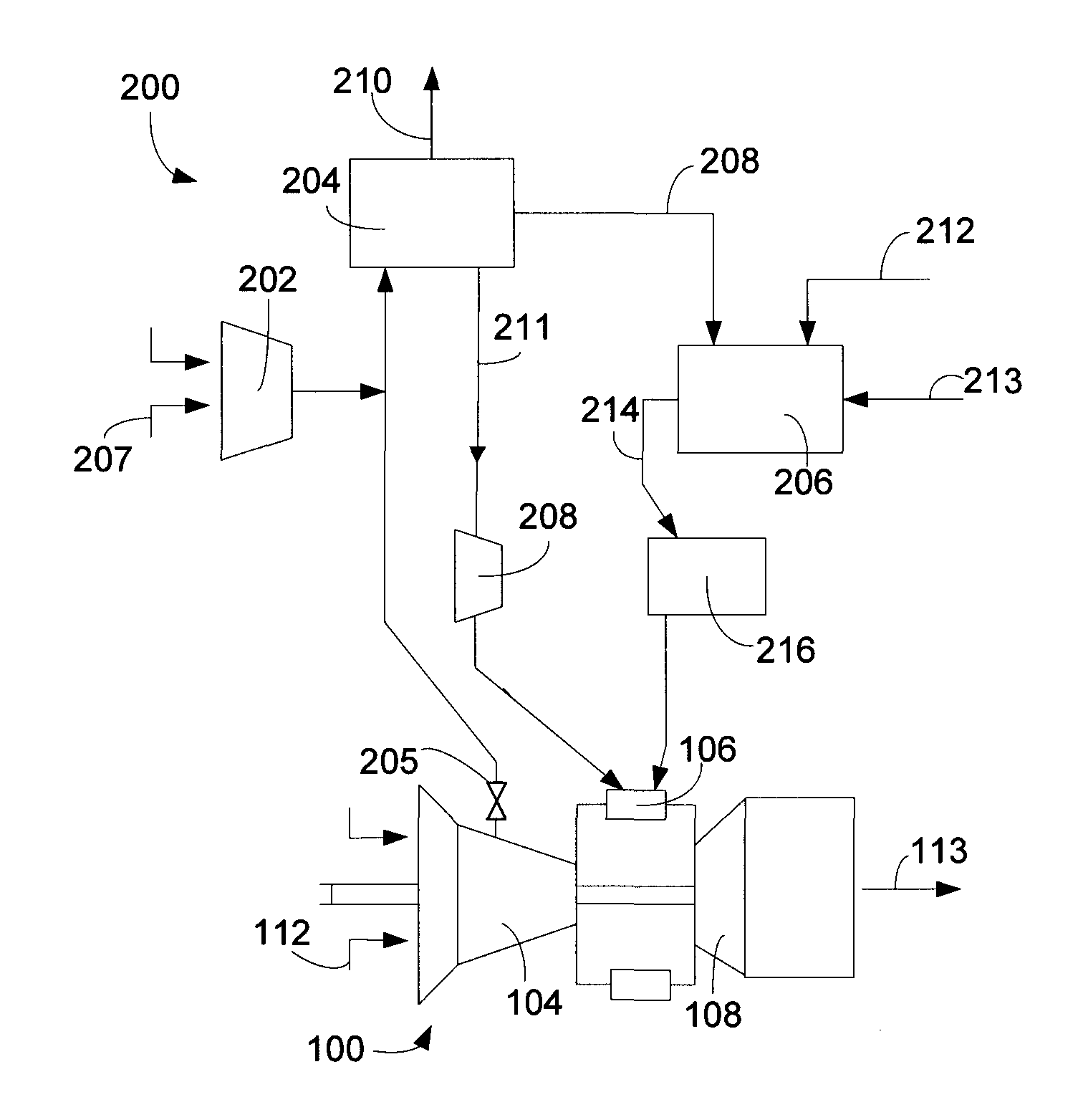
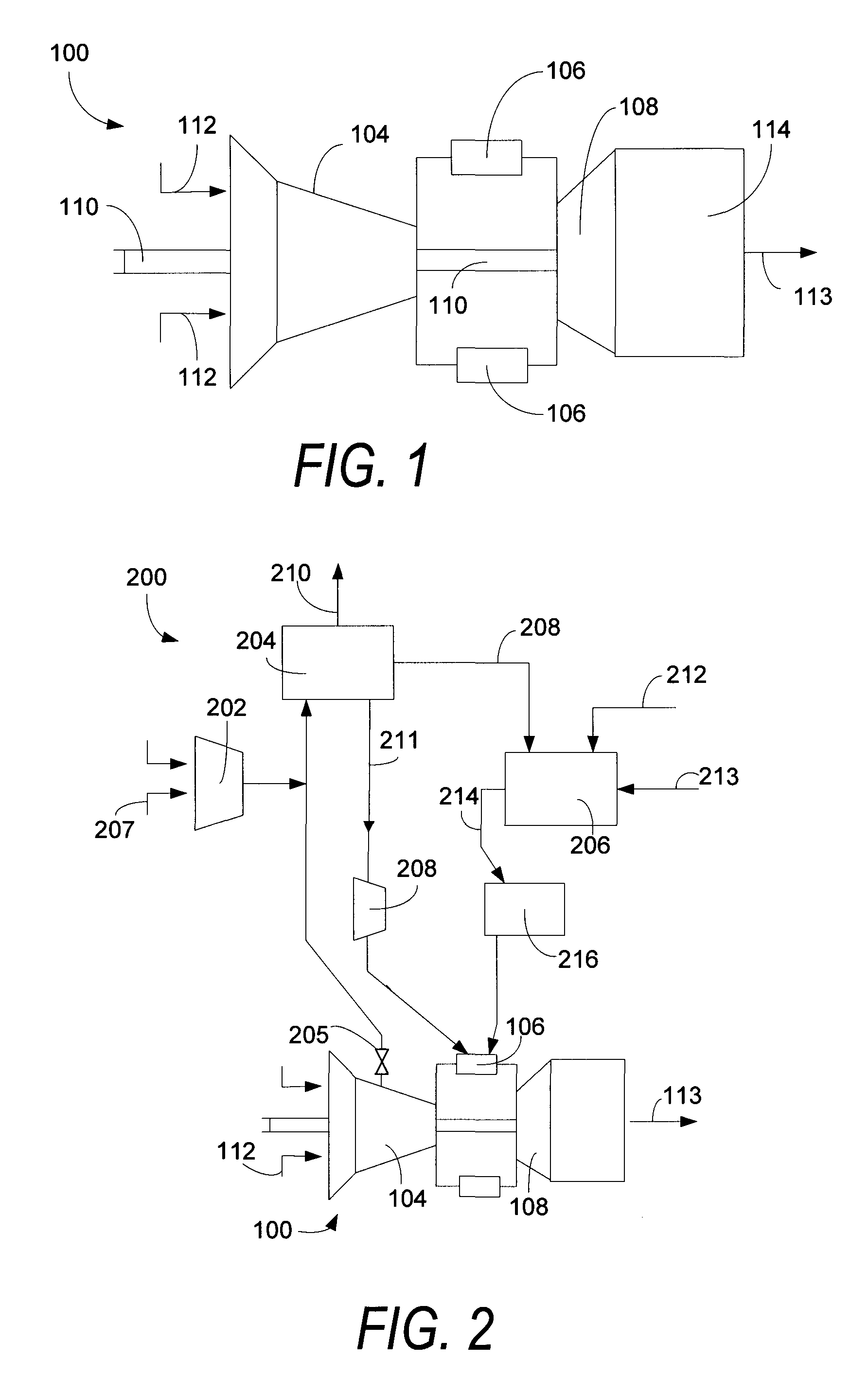
[0025]Referring now to the figures, where the various numbers represent like parts throughout the several views, FIG. 1 demonstrates a schematic illustration of an exemplary gas turbine engine 100 that may be used with certain embodiments of the present application. The gas turbine engine 100 may include a compressor, which also may be known as a turbine compressor 104, a combustor 106, and a turbine 108 connected serially. The turbine compressor 104 and the turbine 108 may be coupled by a shaft 110, which also may couple the turbine 108 and drive an electrical generator (not shown). In certain embodiments, the gas turbine engine 100 may be a 7FB engine, which is commercially available from General Electric Company, although the gas turbine engine 100 illustrated and described herein is exemplary only. Accordingly, the gas turbine engine 100 is not limited to the gas turbine engine shown in FIG. 1 and described herein, but rather, the gas turbine engine 100 may be any gas turbine en...


PUM


Abstract

A method of controlling a load of a gas turbine engine that is part of an integrated gasification combined-cycle power generation system, which includes an air separation unit, that includes the steps of: (1) extracting an amount of compressed air that is compressed by a turbine compressor; (2) supplying the extracted amount of compressed air to the air separation unit; and (3) varying the amount of compressed air extracted from the turbine compressor based upon a desired load for the gas turbine engine.

Description

TECHNICAL FIELD[0001]This present application relates generally to methods for controlling the operation of gas turbine engines. More specifically, but not by way of limitation, the present application relates to methods for controlling the operation of a gas turbine engine that is part of a integrated gasification combined-cycle power generation system by varying the extraction of compressed air from the turbine compressor.BACKGROUND OF THE INVENTION[0002]In current integrated gasification combined-cycle (“IGCC”) power generation systems, an air separation unit is used to supply O2 to a gasifier, which then generates partially combusted gases for use as fuel in a gas turbine. Compressed air is generally supplied to the air separation unit from both a main air compressor and / or through extraction from the discharge of the gas turbine compressor. Currently, the amount of compressed air extracted from the turbine compressor discharge is approximately a fixed percentage of compressor f...

Claims


Application Information

Patent Timeline
Patent Type & Authority Patents(United States)
IPC IPC(8): F02C9/00
CPCF02C3/28F02C6/08F02C9/18Y02E20/16F05D2220/32F05D2270/05Y02E20/18
Inventor WEST, JAMES A.THATCHER, ROBERT T.
Owner GENERAL ELECTRIC CO
Why Eureka
Try Eureka