Measuring instrument for gravimetric moisture determination

a technology of measuring instruments and moisture, applied in instruments, lighting and heating apparatus, furniture, etc., can solve the problem of unavoidable variation in layer thickness from place to place, and achieve the effect of improving the reproducibility of comparison measurements and lowering the measured weight of the sampl

Active Publication Date: 2009-11-17
METTLER TOLEDO GMBH
View PDF9 Cites 8 Cited by
  • Summary
  • Abstract
  • Description
  • Claims
  • Application Information

AI Technical Summary

Benefits of technology

[0016]In principle, a single radiation source would be sufficient for a gravimetric moisture-determination instrument, since its purpose is only to drive the moisture out of the sample while affecting the sample itself as little as possible. The rate of heat generation in the test compartment should therefore not exceed a value that depends on the sample. However, the arrangement taught herein has considerable advantages over the known state of the art. By arranging two radiation sources below and above the sample receiver, one gains significantly better control over the heat distribution in the test compartment and in the sample. The sample is more uniformly heated through and in less time. The intensity of the radiation of both radiation sources can be matched appropriately to the sample and to the sample receiver that is being used. By choosing a suitable temperature profile across the thickness of the layer of the sample spread over the sample receiver, the expulsion of moisture can additionally be speeded up without causing a breakdown of the sample. In spreading the sample over the sample receiver, it is unavoidable that the layer thickness will vary from place to place. The variations depend on the sample and the method of spreading. Due to the improved control over the heat distribution in the sample, the uneven spread of the sample on the sample receiver has less influence on the result of the measurement.
[0045]By conditioning the test compartment before starting the actual measurement, it is possible to achieve stationary conditions in the test compartment, which has a very positive effect on the reproducibility of the measurement results. The reproducibility of results is an important property of a gravimetric moisture-determination instrument. It is an absolute prerequisite to allow comparisons between results. In random-sample tests of process materials such as for example a polymer granulate, the measurement results are compared to empirical reference values. The measurement results and the comparison values are used to determine the pretreatment of the materials and / or the setting data for the processing machines.

Problems solved by technology

In spreading the sample over the sample receiver, it is unavoidable that the layer thickness will vary from place to place.

Method used


Image

  • Measuring instrument for gravimetric moisture determination
  • Measuring instrument for gravimetric moisture determination
  • Measuring instrument for gravimetric moisture determination

Examples


first embodiment

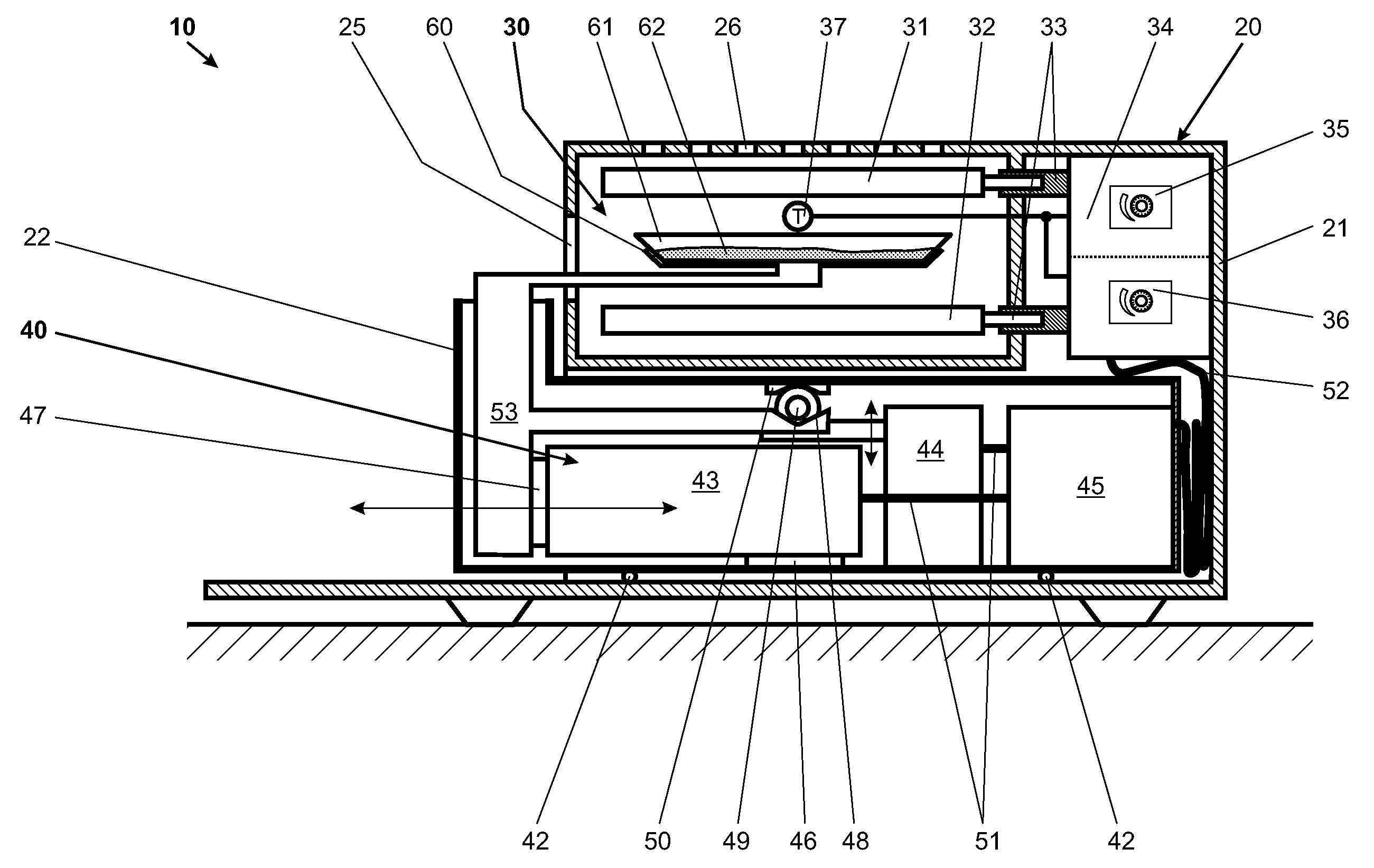
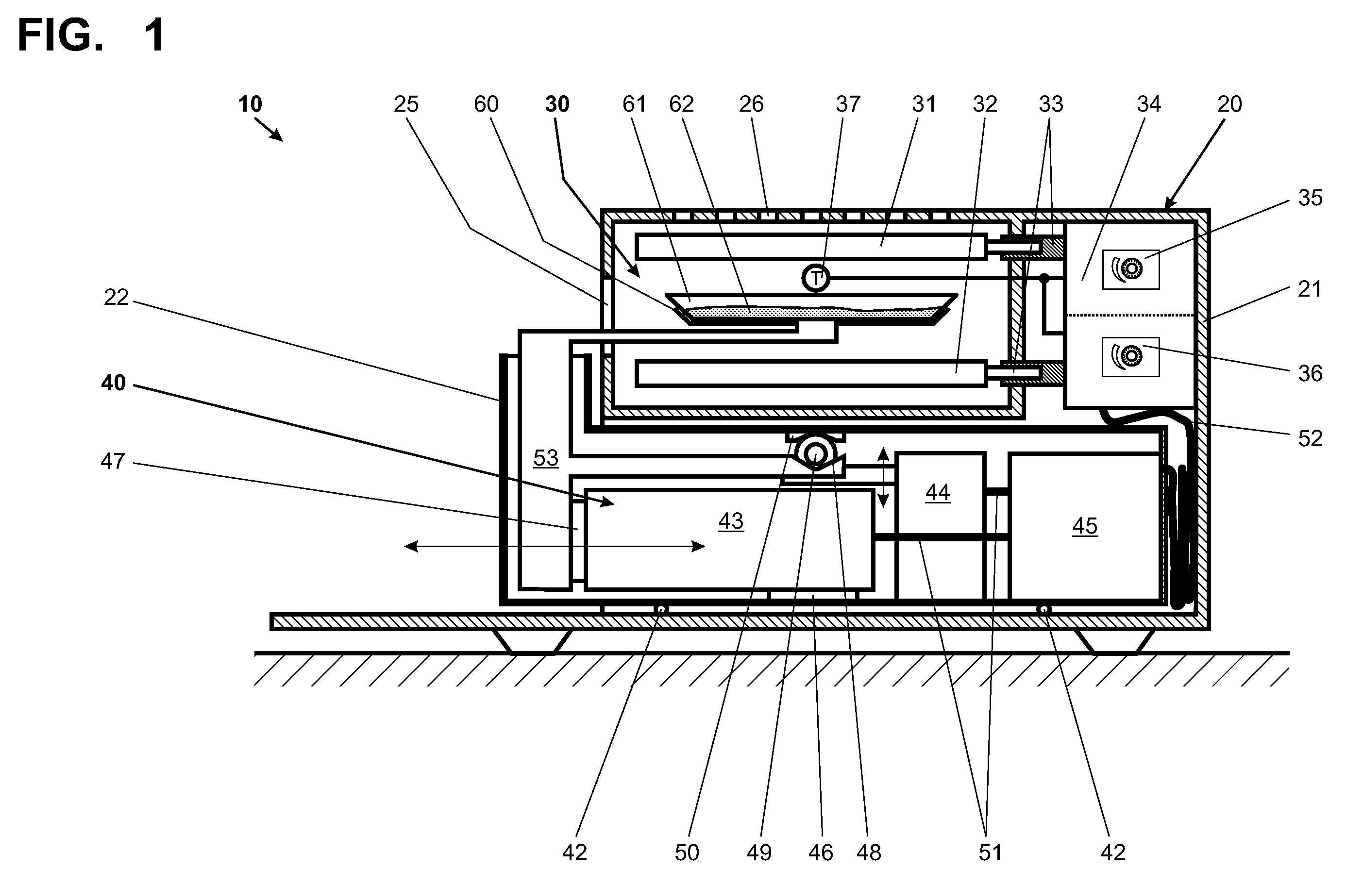
[0079]FIG. 1, in a sectional view, illustrates a measuring instrument 10 in a The measuring instrument 10 has a housing 20 in which a test compartment 30 is arranged. The housing 20 is divided into a movable housing part 22 and a stationary housing part 21. Arranged below the test compartment 30 is a weighing device 40 on the movable housing part 22 which is constrained to a substantially horizontal mode of displacement. The movable housing part 22 glides on rollers 42 (shown only schematically) in the stationary housing 21. Of course, it is also possible to use commercially available drawer guides such as dual pull-out tracks and the like. The movable housing part 22 which is configured as a hollow shell contains a weighing cell 43, a calibration-weight-loading mechanism 44 and at least one electronic module 45 which are connected to each other through communicating means 51. The electronic module 45 contains at least one signal-processing module (not shown in detail here) and in ...

second embodiment

[0085]FIG. 3 represents a cross-sectional view of a second embodiment measuring instrument 110. A weighing device 140 arranged in the housing 120 has substantially the same elements as were named above in the description of FIG. 1 for the weighing device 40. The housing 120 is divided into a stationary housing part 121 and a movable housing part 122.

[0086]Unlike the arrangement of FIG. 1, the weighing device 140 is not arranged in a horizontally movable housing part but in the fixed housing part 121. The weighing device 140 is largely enclosed by the stationary housing part 121. Only a sample receiver 160 which is connected to the weighing device 140 protrudes from the stationary housing part 121 and reaches into the space of the movable housing part 122 when the latter is set in position for performing measurements. Receptacles of different shapes such as sample trays 162, crucibles and the like can be places on this sample receiver 160 which is ring-shaped.

[0087]The movable housin...

fourth embodiment

[0092]FIG. 5 shows a sectional view of the measuring instrument 310 in a A weighing device 340 which is arranged in the housing 320 has substantially the same elements as were described above for the weighing device 40 of FIG. 1. The housing 320 is divided into a stationary housing part 321 and a movable housing part 322. The movable housing part 322 is configured as a lid in which a first radiation source 331 is arranged. As described in the context of FIG. 3, there is a suction device 370 incorporated in the movable housing part 322 above the first radiation source 331. This movable housing part 322 is connected to the stationary housing part 321 through a hinge 329 in the upper portion of the housing 320, with the pivot axis of the hinge 329 being substantially horizontal. The movable housing part 322 forms the upper part of a test compartment 330.

[0093]The lower part of the test compartment 330 is formed in the stationary housing part 321. Arranged in the latter is a second rad...


PUM

PropertyMeasurementUnit
dimensionaaaaaaaaaa
horizontal displacementaaaaaaaaaa
weightsaaaaaaaaaa

Abstract

An instrument for gravimetrically determining the moisture content of a sample has a housing with a weighing device therein. The weighing device has a load-receiving portion and a sample receiver, the latter designed for connection to the load-receiving portion. The housing also contains a test compartment. When set in position to perform a measurement, the sample receiver is disposed inside the test compartment. One embodiment of a means arranged in the test compartment for heating a sample placed on the sample receiver has first and second radiation sources, with the sample receiver arranged therebetween.

Description

CROSS-REFERENCE TO RELATED APPLICATIONS[0001]This application claims a right of priority under 35 USC §119 from European patent application 06 11 3027.4, filed 25 Apr. 2006, the content of which is incorporated by reference as if fully recited herein.TECHNICAL FIELD[0002]The present invention relates to a measuring instrument for the gravimetric determination of moisture content.BACKGROUND OF THE ART[0003]To determine the moisture content in a sample, the sample is dried and the weight of the sample before and after the drying process is determined manually. Due to the extensive amount of work involved, this method is very expensive as well as error-prone.[0004]In some cases, the weight loss can also be measured during the drying process. In a given sample, the decrease in weight is a function of the temperature, the length of the drying time, and the conditions in the test compartment, and it conforms to a weight-versus-time curve which asymptotically approaches the dry weight of t...

Claims


Application Information

Patent Timeline
Patent Type & Authority Patents(United States)
IPC IPC(8): G01N5/02
CPCF26B3/283F26B3/343G01N5/045F26B25/225F26B9/003
Inventor LUCHINGER, PAUL
Owner METTLER TOLEDO GMBH
Why Eureka
Try Eureka