System and method for joint resurface repair

a joint and surface repair technology, applied in the field of devices and methods for the repair of defects, can solve the problems of deterioration of joint function, less durability, and non-typical replacement of cells

Inactive Publication Date: 2009-11-17
ARTHROSURFACE
View PDF327 Cites 150 Cited by
  • Summary
  • Abstract
  • Description
  • Claims
  • Application Information

AI Technical Summary

Problems solved by technology

However, when injured, hyaline cartilage cells are not typically replaced by new hyaline cartilage cells.
While similar, fibrocartilage does not possess the same unique aspects of native hyaline cartilage and tends to be far less durable.
Such cartilage disease or deterioration can compromise the articular surface causing pain and further deterioration of joint function.
Although this procedure has been widely used over the past two decades and can provide good short term results, (1-3 years), the resulting fibrocartilage surface is seldom able to support long-term weight bearing, particularly in high-activity patients, and is prone to wear.
This procedure is technically difficult, as all grafts must be taken with the axis of the harvesting coring drill being kept perpendicular to the articular surface at the point of harvest.
If these plugs are not properly placed in relation to the surrounding articular surface, the procedure can have a very detrimental effect on the mating articular surface.
If the plugs are placed too far below the level of the surrounding articular surface, no benefit from the procedure will be gained.
Further, based on the requirement of perpendicularity on all harvesting and placement sites, the procedure requires many access and approach angles that typ

Method used


Image

  • System and method for joint resurface repair
  • System and method for joint resurface repair
  • System and method for joint resurface repair

Examples


Embodiment Construction

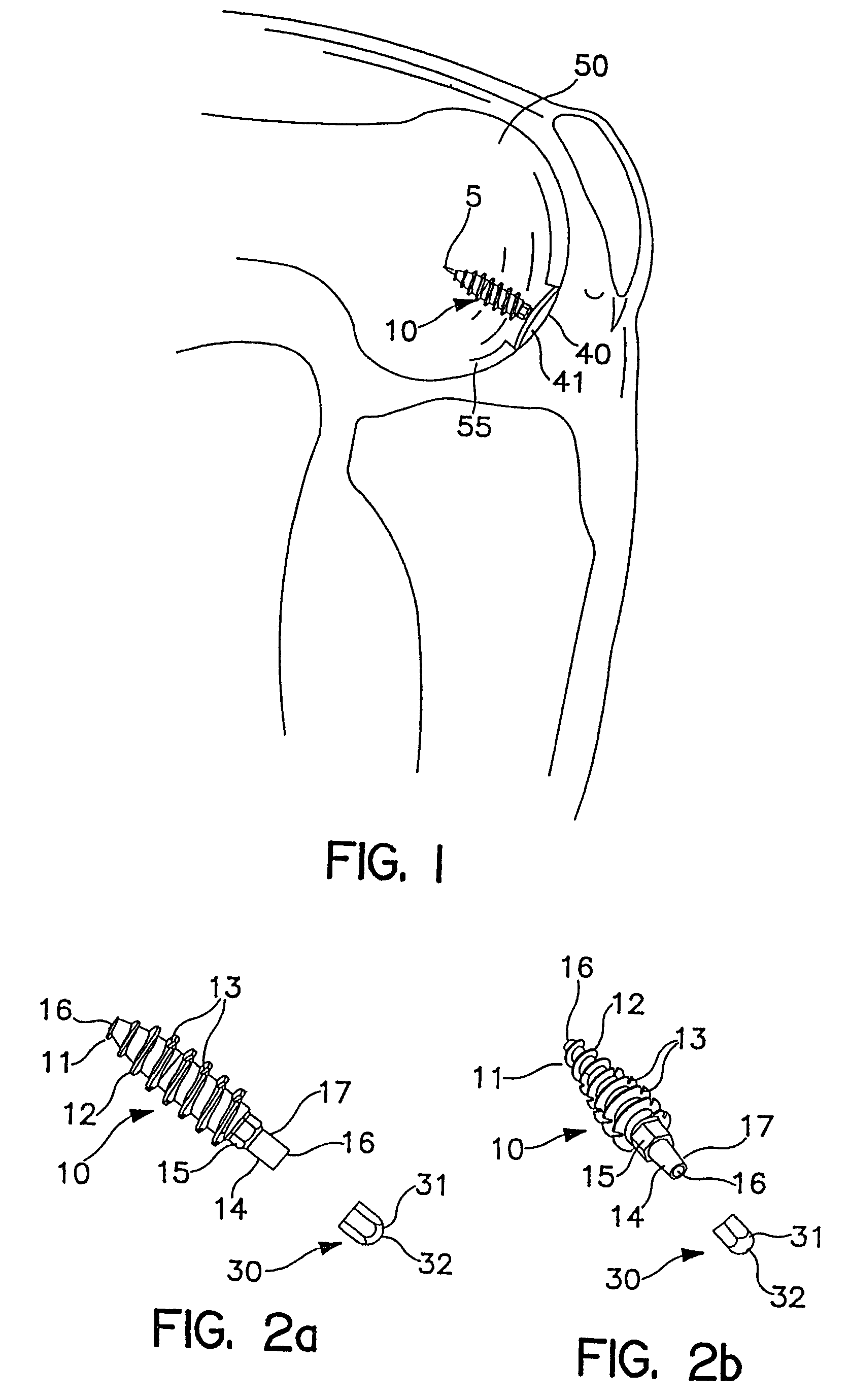
[0153]As an overview, FIG. 1 shows a surgically implanted articular joint surface repair system consistent with the present invention. As shown, the assembled fixation device includes fixation screw 10, implant 40, and anchoring pin 5, implanted in the defect in the medial femoral chondral surface 55 of knee 50. Implant 40 is configured so that bearing or bottom surface 41 of the implant reproduces the anatomic contours of the surrounding articular surface of the knee 50.

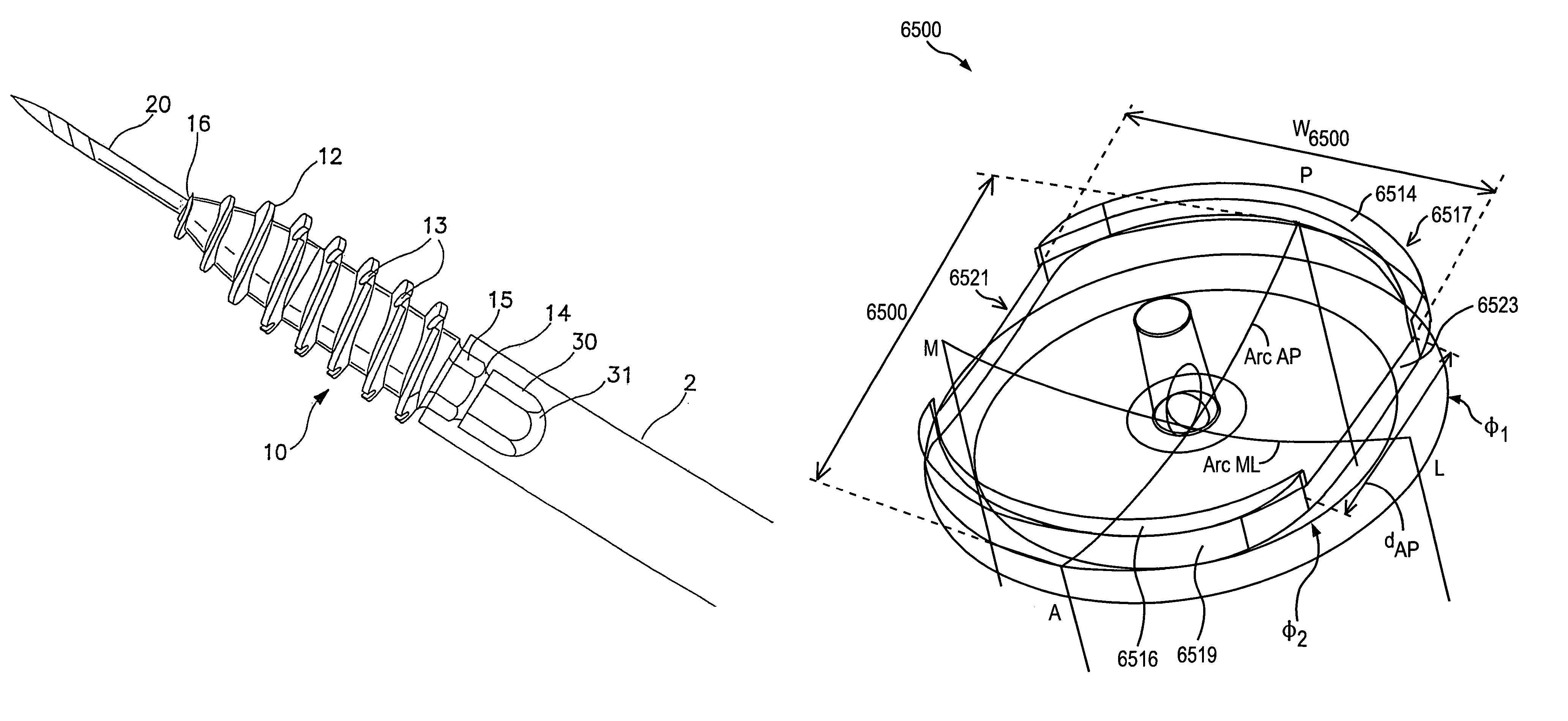
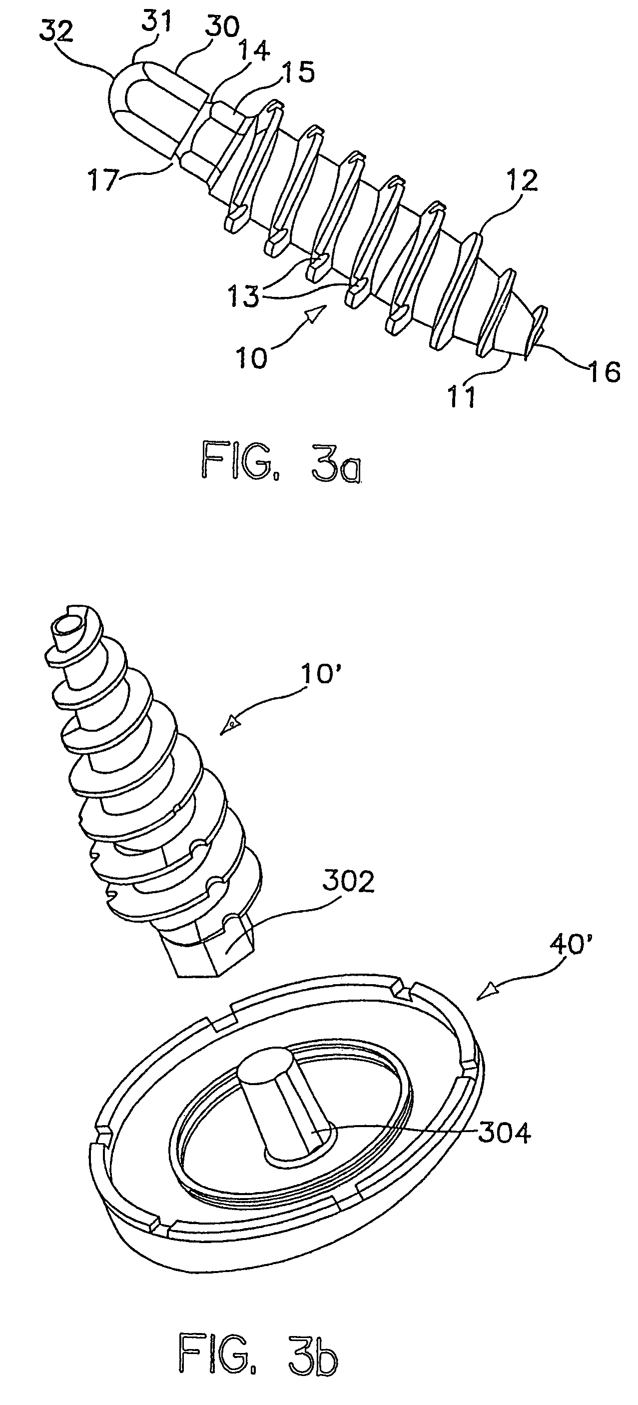
[0154]As illustrated in FIGS. 2a, 2b and 3a, fixation screw 10 comprises threads 12 running the length of the screw from tapered distal tip 11 to hex-shaped drive 15. In the embodiment shown, the screw includes a tapered distal end 11, and aggressive distal threads 12, so that, as screw 10 is driven into the subchondral bone 100 (as shown in FIG. 7a) the screw dilates open and radially compress the subchondral bone, increasing its local density and thereby increasing the fixation strength of the screw. The screw 10 ...


PUM

PropertyMeasurementUnit
Lengthaaaaaaaaaa
Diameteraaaaaaaaaa

Abstract

An implant for installation into a portion of an articular surface includes a protrusion configured to cover an un-excised portion of articular surface proximate to the implant. Another implant may form a cavity to allow the un-excised portion of articular surface to remodel over a perimeter edge of the implant. The implant may also include indentations such as grooves to promote articular cartilage remodeling over a portion of the load bearing surface of the implant. An elongated or non-round implant is also provided having two opposing concentric arcuate shaped sides, as well as a method to seat such an implant in an articular surface. A method for seating an implant without cutting articular cartilage is also provided.

Description

[0001]This application is a continuation application under 37 CFR § 1.53(b) of US application Ser. No. 10 / 162,533 filed Jun. 4, 2002, now U.S. Pat. No. 6,679,917, which is a continuation-in-part application of application Ser. No. 10 / 024,077, filed Dec. 17, 2001, now U.S. Pat. No. 6,610,067 which is itself a CIP application of application Ser. No. 09 / 846,657, filed May 1, 2001, now U.S. Pat. No. 6,520,964 which claims priority from U.S. provisional application Ser. No. 60 / 201,049, filed May 1, 2000, all of which are incorporated herein for reference.FIELD OF THE INVENTION[0002]This invention relates to devices and methods for the repair of defects that occur in articular cartilage on the surface of bones, particularly the knee.BACKGROUND OF THE INVENTION[0003]Articular cartilage, found at the ends of articulating bone in the body, is typically composed of hyaline cartilage, which has many unique properties that allow it to function effectively as a smooth and lubricious load-bearing...

Claims


Application Information

Patent Timeline
IPC IPC(8): A61F2/38A61B17/58A61B17/00A61B17/04A61B17/06A61B17/16A61B17/17A61B17/86A61B17/88A61B19/00A61FA61F2/00A61F2/28A61F2/30A61F2/46
CPCA61B5/1076A61B5/4528A61B17/0401A61B17/1615A61B17/1675A61B17/1764A61B17/8615A61B17/888A61B19/46A61F2/30756A61F2/30942A61F2/4618A61F2/4657A61B1/317A61B5/4514A61B17/0487A61B17/06166A61B17/1635A61B17/1637A61B17/7098A61B17/8625A61B17/863A61B17/8695A61B17/8827A61B17/8875A61B17/8894A61B2017/00238A61B2017/00464A61B2017/0404A61B2017/0409A61B2017/044A61B2017/0445A61B2017/0448A61B2017/045A61B2019/461A61F2/30767A61F2/38A61F2/3859A61F2002/30065A61F2002/30069A61F2002/30113A61F2002/30143A61F2002/30225A61F2002/30299A61F2002/30324A61F2002/30332A61F2002/30354A61F2002/30443A61F2002/30448A61F2002/30451A61F2002/30604A61F2002/30719A61F2002/30772A61F2002/30831A61F2002/30858A61F2002/30871A61F2002/30874A61F2002/30878A61F2002/30879A61F2002/30892A61F2002/30896A61F2002/30943A61F2002/30945A61F2002/30948A61F2002/30952A61F2002/30957A61F2002/4623A61F2002/4635A61F2002/4658A61F2002/4661A61F2002/4662A61F2002/4663A61F2002/4681A61F2210/0071A61F2220/0033A61F2220/0041A61F2220/005A61F2220/0058A61F2230/0006A61F2230/0017A61F2230/0069A61F2230/0093A61F2250/0036A61F2250/0092A61F2310/00017A61F2310/00023A61F2310/00029A61F2310/00059A61F2310/00089A61F2310/00095A61F2310/00203A61F2310/00239A61F2310/00796A61B90/06A61B2090/061A61F2002/30433A61F2002/30873A61F2/4603
Inventor EK, STEVEN W.
Owner ARTHROSURFACE
Why Eureka
Try Eureka