Electrical junction box

a junction box and electrical technology, applied in the field of electric junction boxes, can solve the problems of insufficient heat dissipation of adjacent electrical components, large volume of electrical components, so as to improve the heat dissipation efficiency, reduce the size of the housing, and improve the effect of electrical junction box heat dissipation

Inactive Publication Date: 2009-11-17
AUTONETWORKS TECH LTD +2
View PDF49 Cites 13 Cited by
  • Summary
  • Abstract
  • Description
  • Claims
  • Application Information

AI Technical Summary

Benefits of technology

[0007](1) Bus bars of the bus bar circuit can be bonded to the control circuit board and can have tips bent perpendicular to a body of the control circuit board, and have tab pieces formed at the tips to connect to the power distribution board. The tab pieces formed at the tips of the bus bars face in the direction perpendicular to the control circuit board. Consequently, when connecting the control circuit board to the electrical junction box by inserting the tab pieces into, for example, female fittings disposed in the electrical junction box, even if the tab pieces are flexurally deformed in the direction perpendicular to their body by coming into contact with the female fittings, since the flexural deformation is stopped by the perpendicularly bent portion, no force perpendicular to the body of the bus bars will be applied to the bus bars mounted on the control circuit board. This prevents the heat dissipating means and control circuit board from separating from the bus bars when connecting the control circuit board to the electrical junction box.
[0018]Also, by installing the electrical components on the control circuit board, it is possible to reduce the amount of heat generated on the power distribution board. This reduces or prevents the power distribution board from becoming hot locally.

Problems solved by technology

With the above configuration, however, the electrical components such as relays generate heat when conducting electricity.
The heat emitted from adjacent electrical components does not dissipate sufficiently and may build up gradually.
The heat buildup may cause problems such as deformation of parts and the like, and thus it is desirable to dissipate the heat out of the electrical junction box quickly.

Method used


Image

  • Electrical junction box
  • Electrical junction box
  • Electrical junction box

Examples


Embodiment Construction

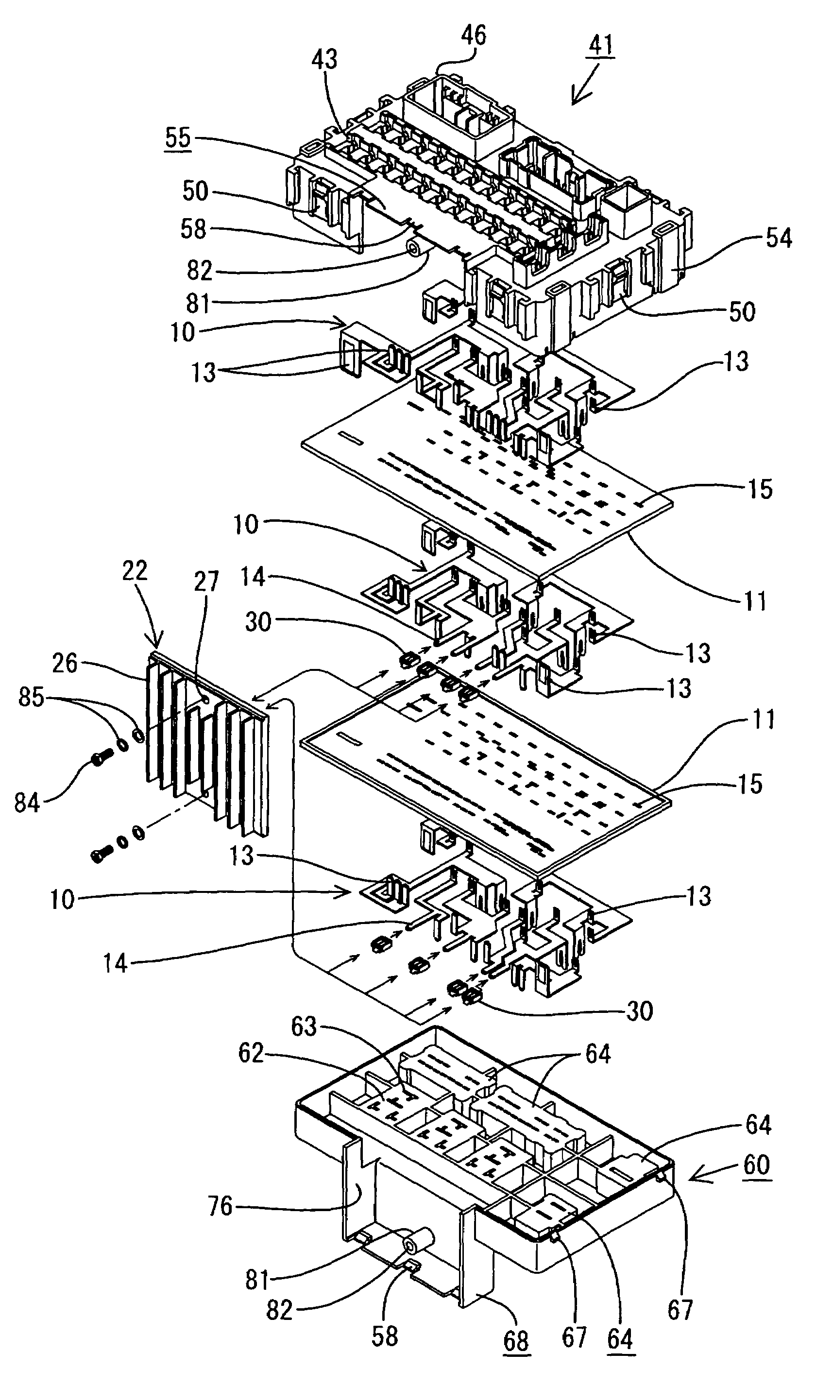
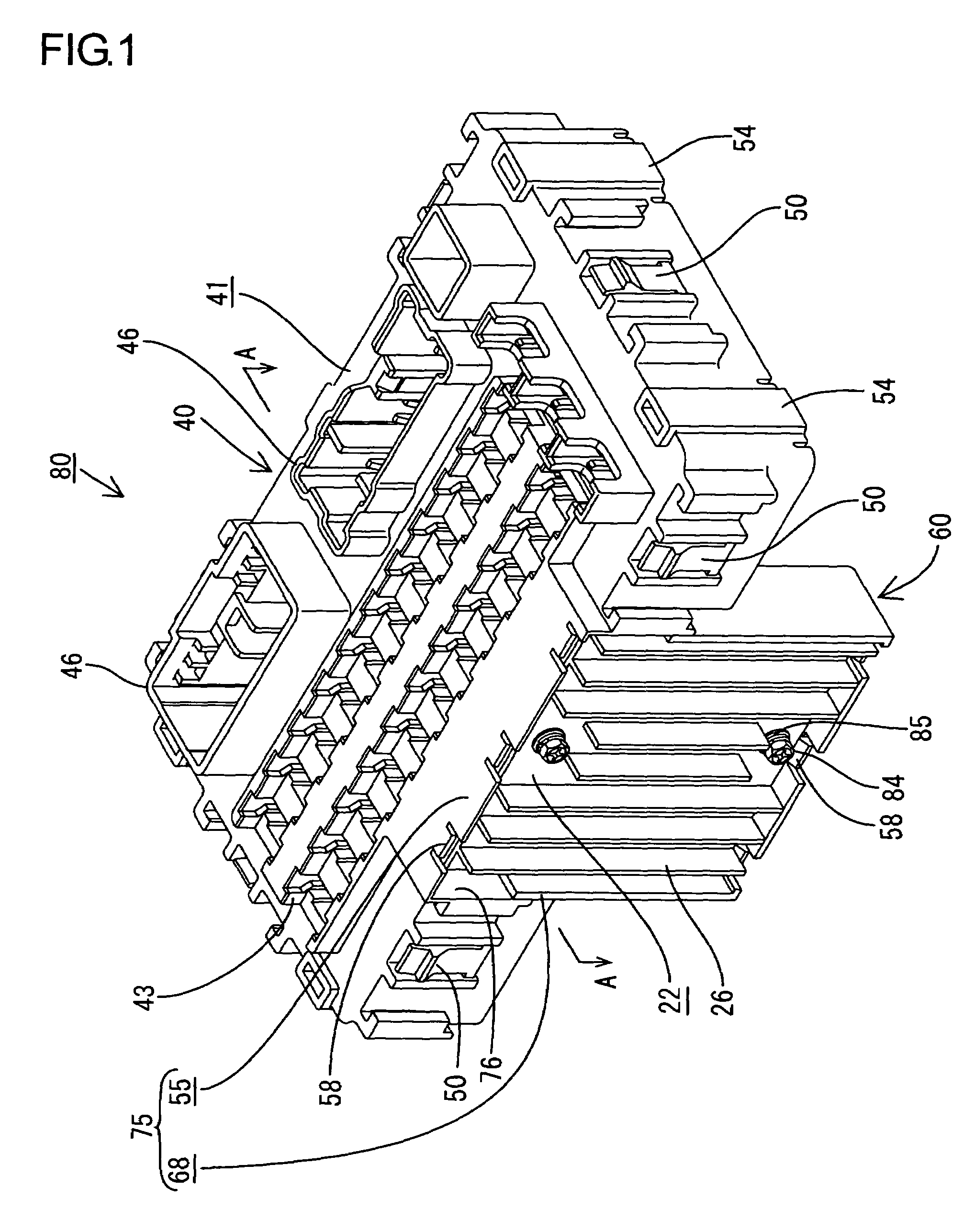
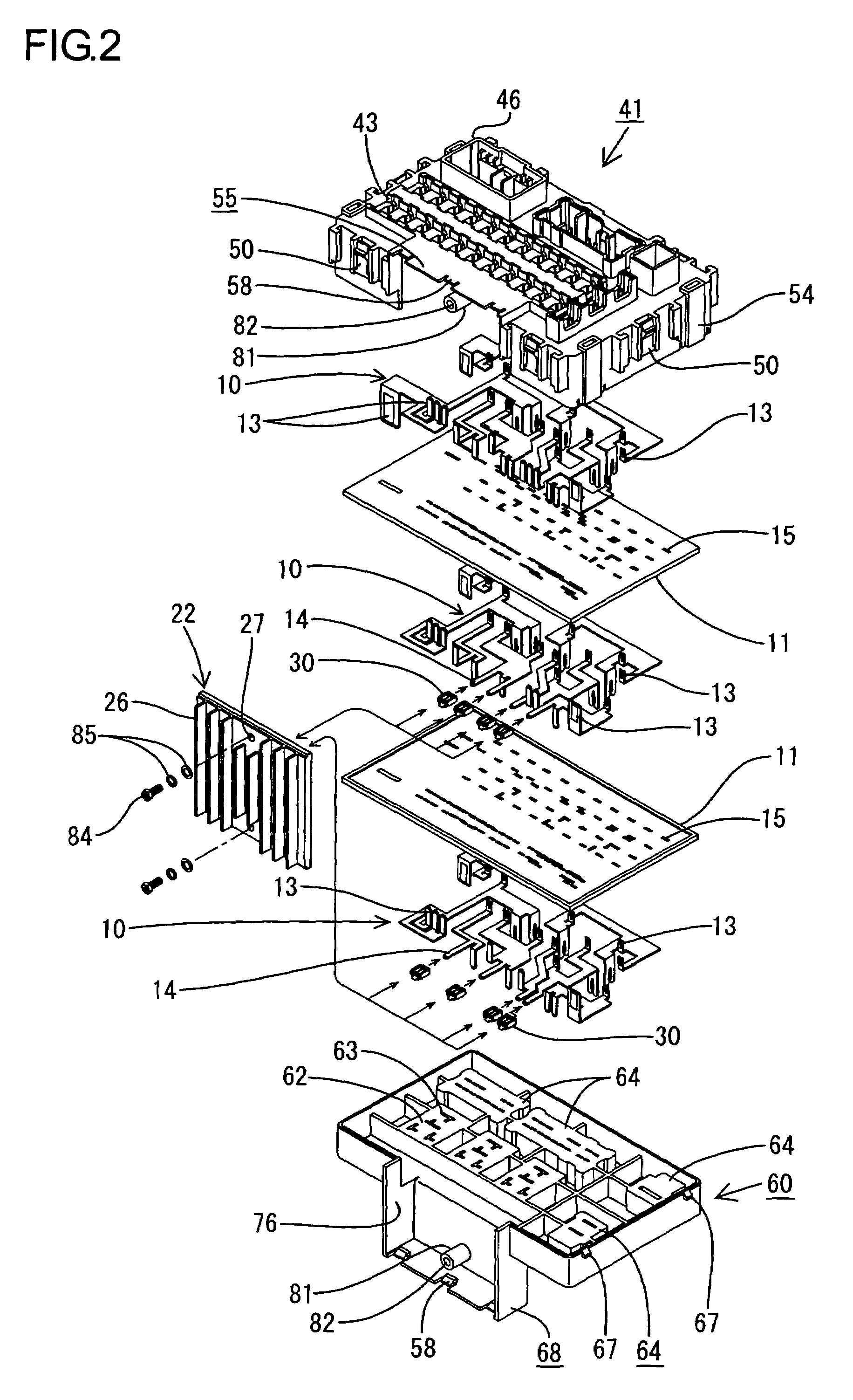
[0038]An exemplary structure of the present invention will be described with reference to FIGS. 1 to 5.

[0039]An electrical junction box 80 according to the exemplary structure consists of a flat housing 40 which houses a power distribution board 12 with its body facing in the up-and-down direction (see FIG. 4). The housing 40 is made of a synthetic resin. It consists of a lower casing 60 and upper casing 41 joined together, where the lower casing 60 has an open top, which is covered by the upper casing 41.

[0040]As shown in FIGS. 3 and 4, on a lower wall of the lower casing 60, there are a relay mount 62 recessed to mount a relay 87 and a connector hood 64 used to connect a wire harness (not shown). Relay terminal insertion slots 63, which vertically penetrate the lower wall of the lower casing 60, are formed in the relay mount 62 to accept power distribution terminals 13 (described later). The power distribution terminals 13 (described later) penetrate a bottom wall of the connector...


PUM


Abstract

The present invention improves heat dissipation of an electrical junction box. An electrical junction box includes a housing which houses a control circuit board disposed perpendicular to a power distribution board. The control circuit board includes a control circuit constructed on one side of an insulating substrate, electrical components mounted on the control circuit, and a heat dissipating means mounted on the other side. The power distribution board includes a plurality of bus bars laminated via a plurality of insulating layers. Consequently, heat generated by the electrical components can be dissipated efficiently by the heat dissipating means, thereby improving heat dissipation of the electrical junction box.

Description

TECHNICAL FIELD[0001]The present invention relates to an electrical junction box consisting of a housing which houses electrical components.BACKGROUND ART[0002]Known electrical junction boxes of this type include, for example, the type disclosed in Japanese Patent Laid-Open No. 8-322127. The electrical junction box consists of a housing which houses a power distribution board composed of a plurality of bus bars disposed along insulating substrates, where electrical components such as relays to be connected to the power distribution board are arranged and mounted on the upper surface of the housing.[0003]With the above configuration, however, the electrical components such as relays generate heat when conducting electricity. The heat emitted from adjacent electrical components does not dissipate sufficiently and may build up gradually. The heat buildup may cause problems such as deformation of parts and the like, and thus it is desirable to dissipate the heat out of the electrical ju...

Claims


Application Information

Patent Timeline
Patent Type & Authority Patents(United States)
IPC IPC(8): H05K7/20
CPCH01R9/226H05K1/14H05K7/026H05K3/202H05K3/366H05K3/0061
Inventor YAMASHITA, HISANOBUMIYAZAKI, KUNIHIRO
Owner AUTONETWORKS TECH LTD
Why Eureka
Try Eureka