Optical division multiplexing transmission and reception method and optical division multiplexing transmission and reception device

a transmission and reception method and optical division multiplexing technology, applied in the field of optical division multiplexing transmission and reception methods and optical division multiplexing transmission and reception devices, can solve problems such as inability to decod

Inactive Publication Date: 2009-11-17
OKI ELECTRIC IND CO LTD
View PDF27 Cites 10 Cited by
  • Summary
  • Abstract
  • Description
  • Claims
  • Application Information

AI Technical Summary

Benefits of technology

[0094]The characteristic of the optical division multiplexing transmission and reception method of the first and second inventions is that the optical code division multiplexing signal generation step included in the transmission step includes a time waveform shaping step that generates a shaped and encoded optical pulse signal by shaping the time waveform of the encoded optical pulse signal. A further characteristic is that the optical code division multiplexing signal extraction step included in the reception step comprises a time waveform restoration step that generates a restored encoded optical pulse signal that is similar to the encoded optical pulse signal waveform by restoring the waveform of the shaped and encoded optical pulse signal.
[0095]Hence, the encoded optical pulse signal is transmitted after the time waveform has been shaped by the time waveform shaping step. In the reception step, the encoded optical pulse signal that has been shaped and transmitted is generated as a restored encoded optical pulse signal that is similar to the encoded optical pulse signal waveform as a result of being restored by the time waveform restoration step.
[0090]On the other hand, with the optical division multiplexing transmission and reception method of the second invention, a shaped and encoded optical pulse signal and an optical time division multiplexing signal are generated in the transmission step and an optical division multiplexing signal is generated as a result of the shaped and encoded optical pulse signal and optical time division multiplexing signal being mixed by the multiplexing step. The optical division multiplexing signal is divided into an optical code division multiplexing reception signal and an optical time division multiplexing reception signal by the branching step that the reception step comprises.
[0097]That is, the optical pulse signal originating in the WDM channel does not undergo the time waveform shaping step during transmission and, therefore, the optical pulse signal originating in the WDM channel contained in the optical wavelength division multiplexing reception signal does not undergo time waveform shaping. The optical pulse signal originating in the WDM channel undergoes time waveform shaping at this stage because the time waveform restoration step is executed even when the optical pulse signal does not undergo time waveform shaping. On the other hand, the encoded optical pulse signal is transmitted after the time waveform has been shaped and the shaped time waveform is restored during reception.
[0098]As described hereinabove, in the reception step, even when an optical pulse signal originating in the WDM channel generated in the optical wavelength division multiplexing signal generation step is mixed in with the encoded optical pulse signal that is transmitted after being shaped, because the time waveform of the optical pulse signal originating in the WDM channel undergoes shaping by the inverse wavelength disperser that is used in the time waveform restoration step, the optical pulse signal is expanded over the time axis. As a result, the peak value of the optical pulse signal originating in the WDM channel drops and can be removed by the first threshold value judgment step.
[0099]Likewise, in the optical division multiplexing transmission and reception method of the second invention, a time waveform shaping step is not included in the optical time division multiplexing signal generation step. As a result, in the reception step, the time waveform of the optical pulse signal originating in the OTDM channel contained in the optical code division multiplexing reception signal is not shaped. The time waveform of the optical pulse signal originating in the OTDM channel is shaped by the inverse wavelength disperser that is used in the time waveform restoration step of the optical code division multiple signal extraction step.
[0100]That is, the optical pulse signal originating in the OTDM channel does not undergo the time waveform shaping step during transmission and, therefore, the optical pulse signal originating in the OTDM channel contained in the received optical code division multiplexing reception signal does not undergo time waveform shaping. The optical pulse signal originating in the OTDM channel undergoes time waveform shaping at this stage because the time waveform restoration step is executed even when the optical pulse signal does not undergo time waveform shaping. On the other hand, the encoded optical pulse signal is transmitted after the time waveform has been shaped and the shaped time waveform is restored during reception.
[0101]As described hereinabove, in the reception step, even when the optical pulse signal originating in the OTDM channel generated in the optical time division multiplexing signal generation step is mixed in with the encoded optical pulse signal that has been shaped and transmitted, the time waveform of the optical pulse signal originating in the OTDM channel undergoes shaping by the inverse wavelength disperser that is used in the time waveform restoration step and the optical pulse signal is expanded over the time axis. As a result, the peak value of the optical pulse signal originating in the OTDM channel drops and can be removed by the first threshold value judgment step.
[0102]Therefore, it can be seen that, according to the optical division multiplexing transmission and reception method of the first invention, OCDM communication and WDM communication can be implemented in parallel. Further, it can be seen that, according to the optical division multiplexing transmission and reception method of the second invention, OCDM communication and OTDM communication can be implemented in parallel. Based on this fact, an optical multiplexing transmission and reception device to which an OCDM channel has been added and an optical multiplexing transmission and reception method can be implemented without changing the usage wavelength bandwidth of the existing WDM channel. Further, an optical multiplexing transmission and reception device to which an OCDM channel has been added and an optical multiplexing transmission and reception method can be implemented without changing the time slot allocated to the existing OTDM channel.
[0103]Furthermore, if the encoder and decoder of the optical division multiplexing transmission and reception device of the first and second inventions are constituted comprising a Fiber Bragg grating, the transmission lines of the optical division multiplexing transmission and reception device are constituted by optical fiber and, therefore, a Fiber Bragg grating formed by using optical fiber has a form that is useful for connection. That is, an optical circulator, as will be described subsequently, is used to form the encoder and decoder, and, therefore, a Fiber Bragg grating is very useful for the connection with the optical circulator.
[0105]Further, the first and second threshold value judgment sections of the optical division multiplexing transmission and reception device of the first and second inventions is preferably constituted comprising a light saturable absorber. It is confirmed that the threshold value judgment section that uses a light saturable absorber possesses resistance to light destruction and mechanical destruction as well as water resistance and has a very long lifespan. Therefore, the threshold value judgment section that uses a light saturable absorber is preferably used in the optical multiplexing transmission and reception device.

Problems solved by technology

Hence, unless the code used to encode the transmitted optical pulse signal is published, a third party who is unaware of the code is unable to decode the encoded optical pulse signal.

Method used


Image

  • Optical division multiplexing transmission and reception method and optical division multiplexing transmission and reception device
  • Optical division multiplexing transmission and reception method and optical division multiplexing transmission and reception device
  • Optical division multiplexing transmission and reception method and optical division multiplexing transmission and reception device

Examples


first embodiment

[0127]An optical division multiplexing transmission and reception method of the first embodiment and a device for implementing the optical division multiplexing transmission and reception method will be described with reference to FIG. 5. The optical division multiplexing transmission and reception device comprises a transmission section 500 that comprises in parallel an optical code division multiplexing signal generation section 510 and an optical wavelength division multiplexing signal generation section 530 and a reception section 600 that comprises in parallel an optical code division multiplexing signal extraction section 610 and an optical wavelength division multiplexing signal extraction section 630.

[0128]In the following description, the optical code division multiplexing signal generation section is abbreviated to the OCDM signal generation section, the optical wavelength division multiplexing signal generation section is abbreviated to the WDM signal generation section, ...

second embodiment

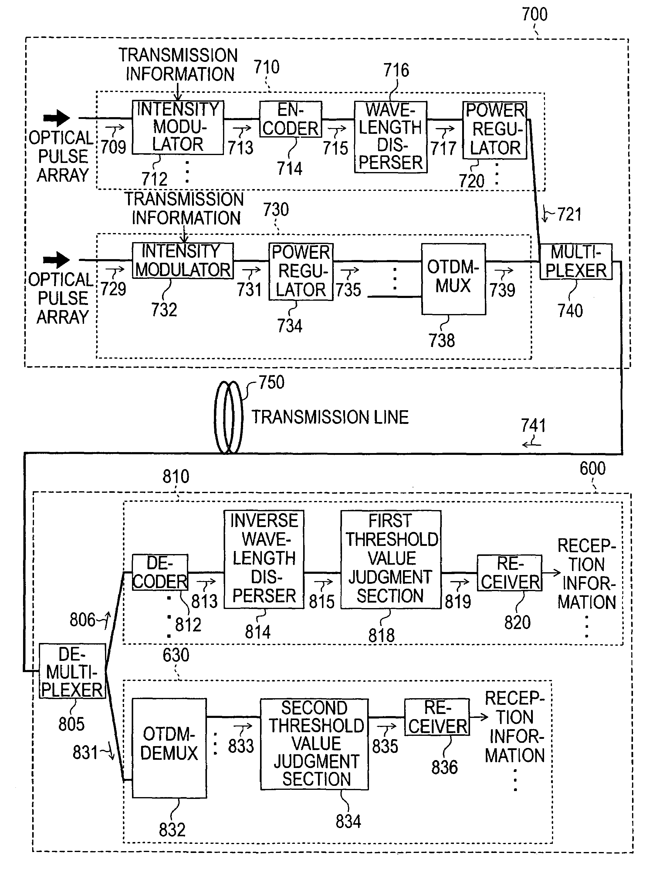
[0208]An optical division multiplexing transmission and reception method and a device for implementing this method of the second embodiment will be described with reference to FIG. 11. The optical division multiplexing transmission and reception device comprises a transmission section 700 that comprises in parallel an optical code division multiplexing signal generation section 710 and an optical time division multiplexing signal generation section 730, and a reception section 800 that comprises in parallel an optical code division multiplexing signal extraction section 810 and an optical time division multiplexing signal extraction section 830.

[0209]In the subsequent description, the optical time division multiplexing signal generation section is also abbreviated as OTDM signal generation section and the optical time division multiplexing signal extraction section is also abbreviated as the OTDM signal extraction section.

[0210]The constitution of an OCDM signal generation section 7...


PUM


Abstract

An object of the present invention is to implement optical multiplexing transmission and reception in which an OCDM channel is added without changing the used wavelength bandwidth of the existing WDM channel or without changing the time slot allocated to the existing OTDM channel. Hence, one of the embodiments of the present invention is constituted as follows. The OCDM signal generation section generates an encoded optical pulse signal by encoding an optical pulse signal. The encoded optical pulse signal is inputted to the wavelength disperser and the time waveform of the encoded optical pulse signal is shaped to be outputted as a shaped and encoded optical pulse signal. The WDM signal generation section generates an optical wavelength division multiplexing signal. The OCDM signal extraction section decodes the OCDM reception signal by using the same code as the time-spreading / wavelength-hopping code for each channel and generates a decoded OCDM reception signal. The shaped and encoded optical pulse signal component that is contained in the decoded OCDM reception signal is restored by the inverse-wavelength disperser and a reproduced optical pulse signal is generated. Only the autocorrelation waveform component of the optical pulse signal constituting the OCDM transmission signal is extracted from the reproduced optical pulse signal by the first threshold value judgment section. In the WDM signal extraction section, the second threshold value judgment section extracts the WDM signal of each channel from the WDM reception signal.

Description

BACKGROUND OF THE INVENTION[0001]1. Field of the Invention[0002]The present invention relates to an optical division multiplexing transmission and reception method and an optical division multiplexing transmission and reception device and, more particularly, to a method and device that make it possible for wavelength division multiplexing (WDM) transmission and reception and optical code division multiplexing (OCDM) transmission and reception to coexist. Further, the present invention relates to a method and device that make it possible for optical time division multiplexing (OTDM) transmission and reception and OCDM transmission and reception to coexist.[0003]2. Description of Related Art[0004]In order to increase the speed or capacity of optical fiber communications, an optical division multiplexing technology that transmits a plurality of channels' worth of optical pulse signals all together on one optical fiber transmission line has been investigated. As means for the optical di...

Claims


Application Information

Patent Timeline
Patent Type & Authority Patents(United States)
IPC IPC(8): H04B10/00H04B1/69H04B1/713H04B1/717H04B10/524H04B10/54H04B10/58H04J3/00H04J14/00H04J14/02H04J14/04H04J14/06
CPCH04J14/005H04J14/02
Inventor MINATO, NAOKIKAMIJOH, TAKESHI
Owner OKI ELECTRIC IND CO LTD
Why Eureka
Try Eureka