Wireless transmission system and method for wirelessly transmitting data signals in a flight vehicle

a transmission system and flight vehicle technology, applied in the direction of transmission monitoring, wireless commuication services, aircraft crew accommodation, etc., to achieve the effect of reducing the cost of changing the seating configuration, facilitating the change of seating configuration, and improving the in-service rate of the aircra

Active Publication Date: 2009-11-17
PANASONIC CORP
View PDF15 Cites 39 Cited by
  • Summary
  • Abstract
  • Description
  • Claims
  • Application Information

AI Technical Summary

Benefits of technology

[0013]The present invention is directed to solving this problem, and an object of the invention is to build a system that can assure transmission capacity sufficient to carry large amounts of video data without adversely affecting or being affected by the terrestrial wireless telephone network.
[0016]The wireless transmission system and method of the present invention wirelessly transmit data signals to each seat. As a result, changing the wiring is not needed when changing the seating configuration, the seating configuration can thus be changed in a short time, the in-service rate of the aircraft can be improved, and the cost of changing the seating configuration can be reduced. Furthermore, because the wireless frequency band is changed based on the altitude zone where the aircraft is flying, a frequency band that is limited to prevent mutual interference with ground communication systems can be used when flying at low altitude to provide the minimum required services. Furthermore, because there is no interference with the ground communication system or interference from the ground communication system when flying at high altitude, a wide frequency band can be used to provide more advanced services such as video-on-demand. As a result, the need for advanced in-flight services can be met while also reducing wireless interference with the ground communication system.

Problems solved by technology

Furthermore, because the wireless frequency band is changed based on the altitude zone where the aircraft is flying, a frequency band that is limited to prevent mutual interference with ground communication systems can be used when flying at low altitude to provide the minimum required services.

Method used


Image

  • Wireless transmission system and method for wirelessly transmitting data signals in a flight vehicle
  • Wireless transmission system and method for wirelessly transmitting data signals in a flight vehicle
  • Wireless transmission system and method for wirelessly transmitting data signals in a flight vehicle

Examples


first embodiment

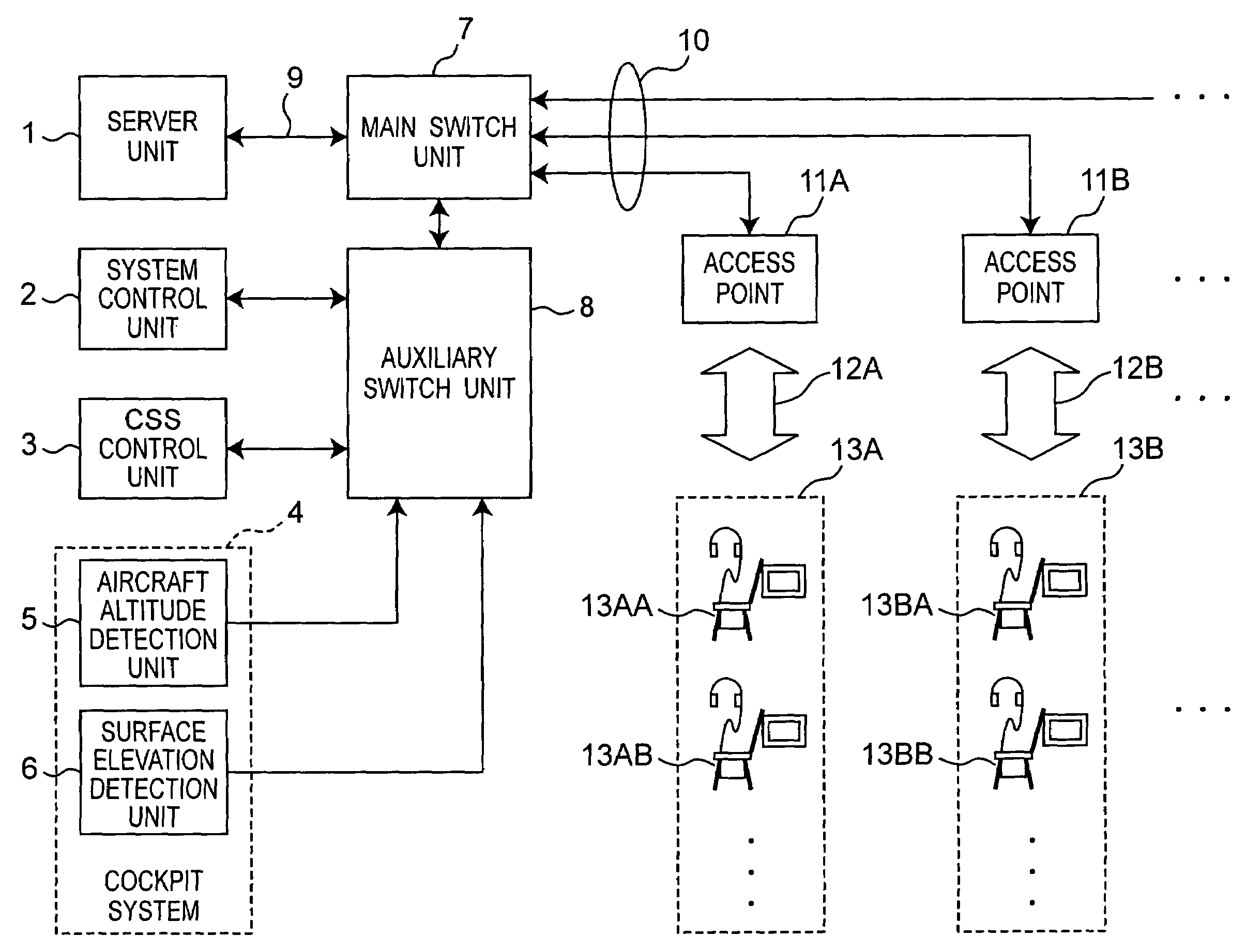
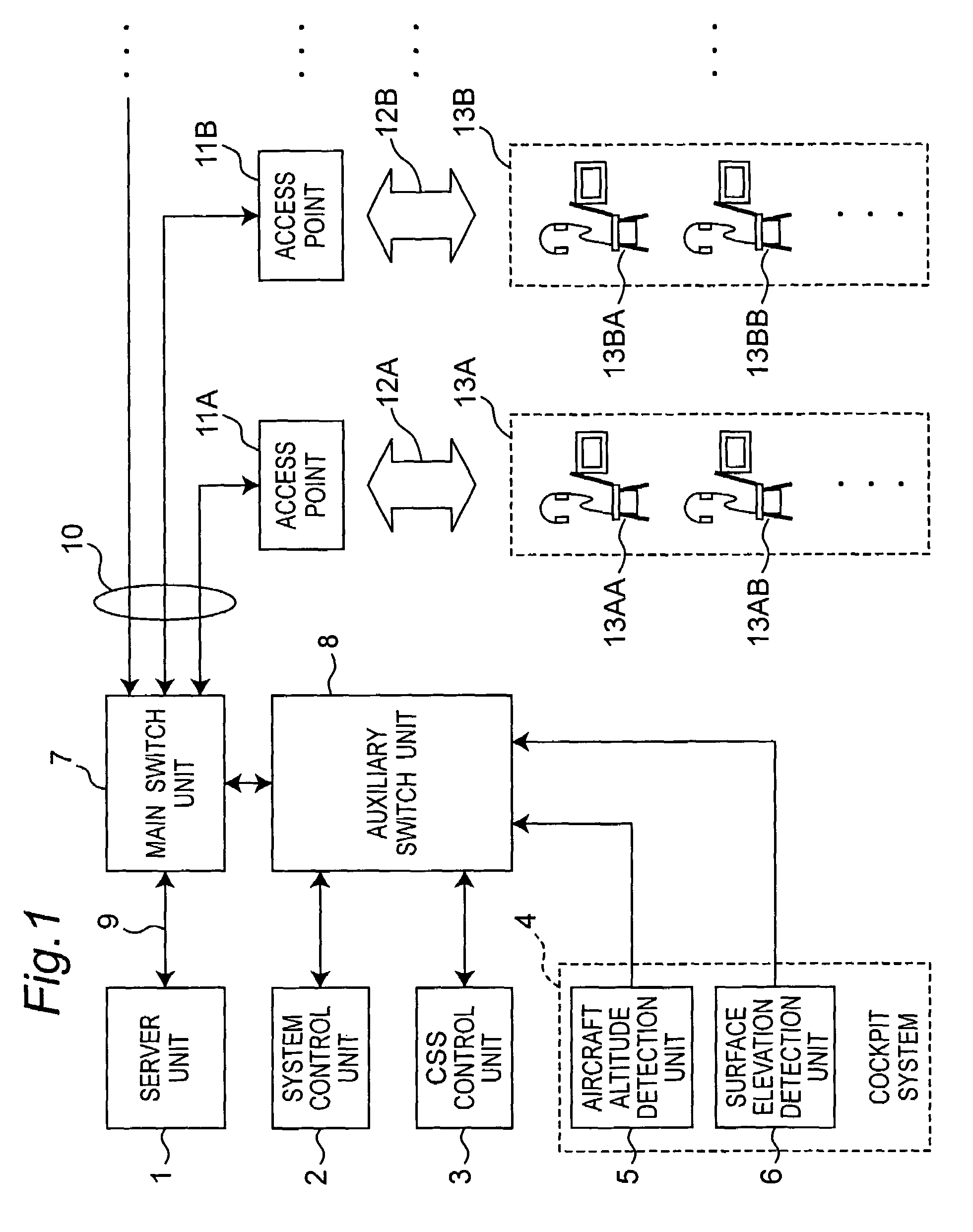
[0031]FIG. 1 is a block diagram showing the general arrangement of the first embodiment of the invention. This first embodiment of the invention is installed inside an aircraft. The aircraft may be an airplane with jet engines or propellers, for example, a helicopter, a hovercraft, a balloon tethered to the ground, a rocket, a man-made satellite, a space station, or any other type of craft that can remain aloft at a predetermined distance or more from the Earth's surface for at least a predetermined period of time. This first embodiment of the invention is described using a passenger plane by way of example only. There may be several hundred passenger seats installed in the airplane, and passengers can enjoy movies, audio programming, games, and Internet browsing by an in-flight entertainment (IFE) system.

[0032]Referring to FIG. 1, the server unit 1 includes a hard disk array for storing data signals including at least one of a video signal or an audio signal, and an AV server for r...

second embodiment

[0097]This second embodiment of the invention differs from the first embodiment in the allocation of wireless channels as further described below. Other aspects of the arrangement, operation, and effect of this second embodiment are the same as the first embodiment, and further description thereof is thus omitted.

[0098]FIG. 6A and FIG. 6B describe different methods of allocating the wireless channels shown in FIG. 4 to different parts of the airplane. The arrangements shown in FIG. 6A and FIG. 6B differ from the arrangements shown in FIG. 5A and FIG. 5B only in that the wireless zones indicated by dotted lines and the wireless channel allocated to each wireless zone are different.

[0099]FIG. 6A shows the zone and channel allocation when in the first altitude zone, at which time the wireless channels C36, C44, C40, and C48 in the F1 frequency band are allocated for first service use. The first services must normally be delivered to all parts of the airplane, and the same content is di...

third embodiment

[0101]The allocation of wireless channels in this third embodiment differs from the allocation in the first and second embodiments. Other aspects of the arrangement, operation, and effect of this second embodiment are the same as the first embodiment, and further description thereof is thus omitted.

[0102]FIG. 9A and FIG. 9B describe another method of allocating the wireless channels shown in FIG. 4 to different parts of the airplane. The arrangements shown in FIG. 9A and FIG. 9B differ from the arrangements shown in FIG. 5A and FIG. 5B only in that the wireless zones indicated by dotted lines and the wireless channel allocated to each wireless zone are different.

[0103]FIG. 9A shows the zone and channel allocation when in the first altitude zone, at which time the wireless channel C36 in the F1 frequency band is allocated for first service use. Wireless channel C36 is suited for use with the first services because the first services must be provided throughout the aircraft and wirele...


PUM


Abstract

Changing the seating configuration when there are wired connections to each seat is difficult. A wireless transmission system and method communicate wirelessly while also preventing interference with the ground communication system. The wireless transmission system wirelessly transmits data signals inside the aircraft, and has an altitude zone identification arrangement for determining in which of N altitude zones the aircraft is flying, access points that can transmit the data signals wirelessly on any one frequency band selected from among M frequency bands, client units for receiving the data signals, and a selection unit for selecting one of the M frequency bands based on the altitude zone in which the aircraft is flying. The altitude zone identification arrangement includes an aircraft altitude detection unit and system control unit, and the selection unit includes the system control unit.

Description

BACKGROUND OF THE INVENTION[0001]1. Field of Technology[0002]The present invention relates to wireless transmission technology for effectively utilizing frequency bands to maximize transmission capacity in airplanes and other types of aircraft.[0003]2. Description of Related Art[0004]In-flight entertainment (“IFE”) systems used in passenger planes in recent years have helped make long-distance flights more enjoyable by providing passengers with in-flight entertainment services such as movies, audio programming, games, and even Internet browsing. The movies, audio programming, Internet data, and other information accessible by these systems are typically stored in an on-board server, and delivered from the server by coaxial cable, optical fiber, or other wired medium as either analog or digital transmissions. IFE equipment generally includes a ceiling-mounted projector and an LCD or other type of video monitor, as well as compact, individual monitors and controllers (handsets) instal...

Claims


Application Information

Patent Timeline
Patent Type & Authority Patents(United States)
IPC IPC(8): H04B7/15H04B1/034H04W4/00H04B1/40H04B15/00H04B17/00H04B7/00B64D11/00H04W16/02H04W16/12H04W84/00
CPCH04B7/18508
Inventor HIGASHIDA, MASAAKISAKANISHI, YASUAKIEZAKI, TOSHIHIRO
Owner PANASONIC CORP
Why Eureka
Try Eureka