Split thread orthopaedic implant impactor

a technology of impactors and split threads, applied in the field of orthopaedic instruments, can solve the problems of difficult cleaning and sterilization of impactors after surgery, difficult to properly align, and difficult to disconnect the head from the cup, etc., and achieves the effect of convenient cleaning and sterilization, time-saving use for surgeons, and convenient us

Inactive Publication Date: 2009-11-24
SYMMETRY MEDICAL MFG INC
View PDF46 Cites 52 Cited by
  • Summary
  • Abstract
  • Description
  • Claims
  • Application Information

AI Technical Summary

Benefits of technology

[0014]An advantage of the present invention is that it is easy to use in a minimally invasive surgical procedure.
[0015]Another advantage of the present invention is that it is time efficient for the surgeon to use, particularly with respect to engaging and disengaging the acetabular cup.
[0016]Yet another advantage of the present invention is that it is easy to clean and sterilize.
[0017]Yet another advantage of the present invention is that the impaction collar subassembly is easily removed from the impactor.
[0018]Yet another advantage of the present invention is that the impaction collar subassembly is easily installed onto the impactor.
[0019]Yet another advantage of the present invention is that the impaction collar subassembly can be compatible with many different manufacturer's styles of acetabular cups.

Problems solved by technology

Particularly in a minimally invasive procedure, where a small incision is made to reduce the trauma to surrounding tissue, at least two problems occur in seating an acetabular cup.
It is difficult to properly align the impactor because of anatomical features that are in the way, and disconnecting the head from the cup is more difficult with limited access to the end of the tool.
Cleaning and sterilization of the impactor after surgery can also be difficult.
A problem with this design is that it requires the threaded stud to be threaded into the acetabular cup, and this threading process can be tedious and time consuming, and can result in crossthreading the threaded stud into the acetabular cup with a resultant less than secure connection between the threaded stud and the acetabular cup.
Another problem with this design is that it is substantially closed along the shaft which makes the internal components, such as the swivel drive, difficult to clean and sterilize.
Further, it is largely a closed design which makes the drive train difficult to clean and sterilize.

Method used


Image

  • Split thread orthopaedic implant impactor
  • Split thread orthopaedic implant impactor
  • Split thread orthopaedic implant impactor

Examples


Embodiment Construction

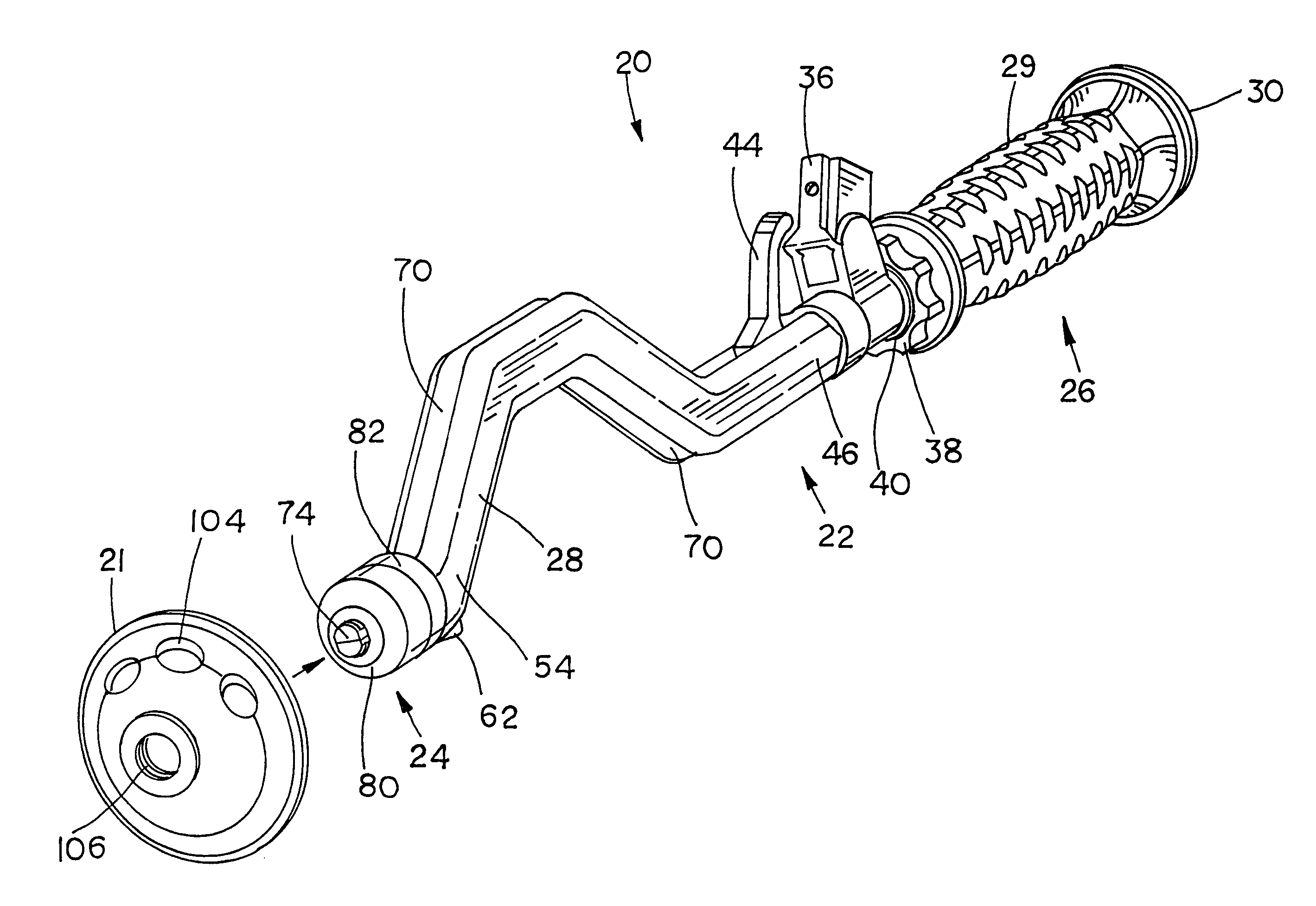
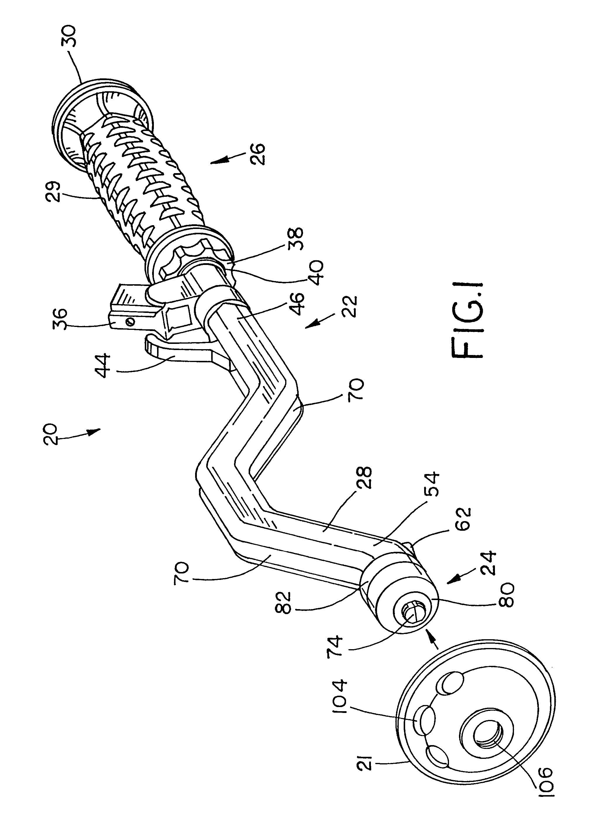
[0041]Referring now to the drawings, and more particularly to FIG. 1, there is shown an orthopaedic implant impactor 20 and an orthopaedic implant 21 shown as an acetabular cup prosthesis.

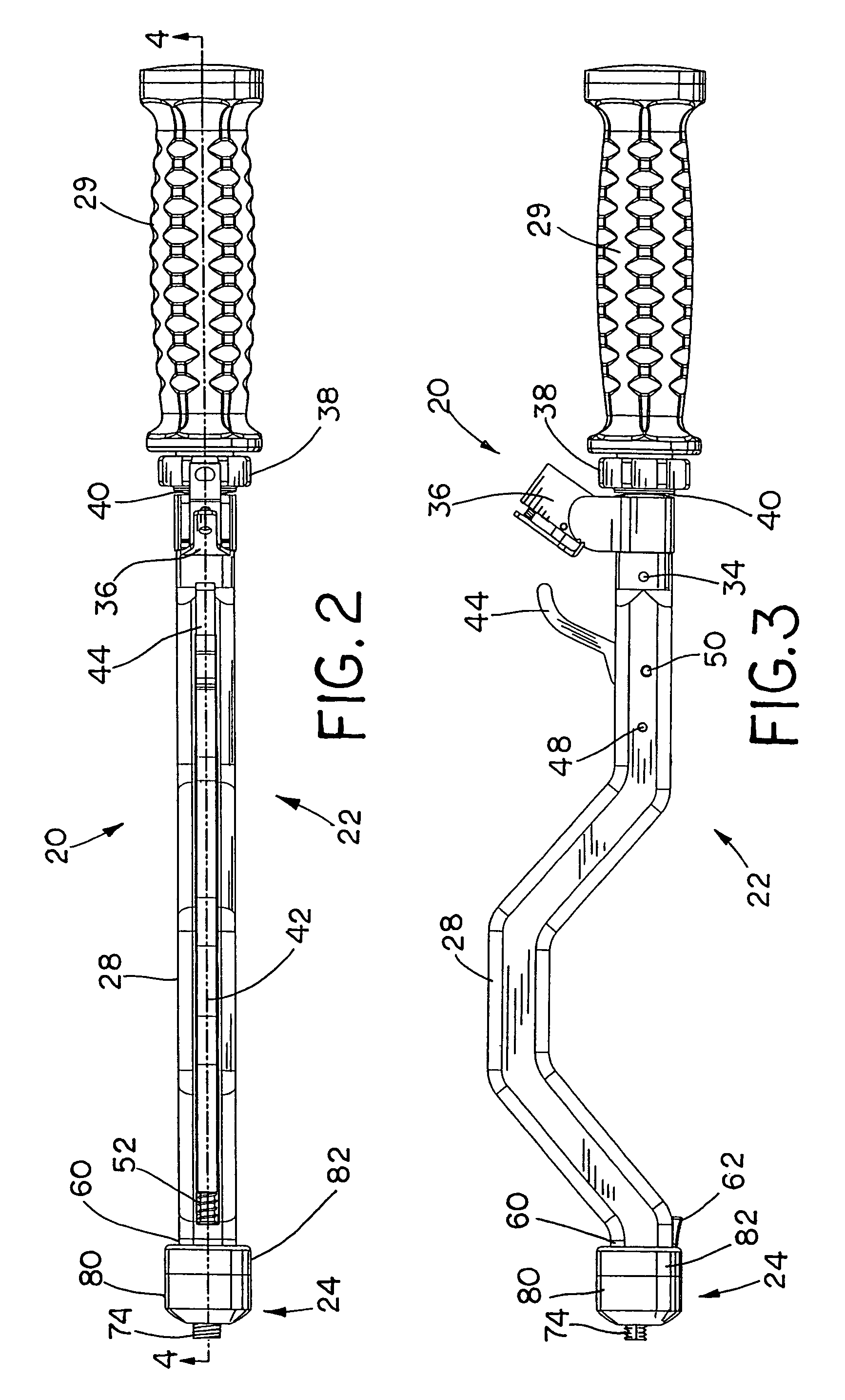
[0042]Shown more particularly in FIGS. 2-6, impactor 20 includes impaction tool subassembly 22 and impaction collar subassembly 24. Impaction tool subassembly 22 includes handle subassembly 26 connected to impactor shaft 28. Handle subassembly 26 includes a handle 29, a strikecap 30 connected to handle shaft 32, and handle shaft 32 can be fixedly connected to impactor shaft 28 using pin 34. Impaction tool subassembly 22 further includes alignment guide subassembly 36 which is rotatable around handle shaft 32, and which can be fixed in place by tightening alignment guide lock nut 38 against washer 40 and alignment guide subassembly 36. Push rod 42 and cam lock lever or trigger 44 are both connected to distal end 46 of impactor shaft 28 at pins 48 and 50, respectively. Push rod 42 is biased against t...


PUM


Abstract

An orthopaedic implant impactor which includes a shaft having a proximal end and a distal end. A trigger is pivotably connected to the distal end, the trigger having a cam end. A push rod is within the shaft and is connected to the cam end of the trigger.

Description

BACKGROUND OF THE INVENTION[0001]1. Field of the Invention[0002]The present invention relates to orthopaedic instruments, and, more particularly, to orthopaedic implant impactors.[0003]2. Description of the Related Art[0004]The hip joint is configured as a ball and socket arrangement which includes the femoral head joined to the natural socket or acetabulum located in the pelvis. Deterioration of the acetabulum and / or femoral head can be brought about by injury or progressive diseases such as osteoarthritis. When injury or disease occurs, the damaged component(s) can be replaced or rebuilt using appropriate orthopaedic implants. In the technique known as a “total hip replacement”, one method involves cementing or press-fitting an acetabular cup prosthesis into the acetabulum after the acetabulum has been sufficiently reamed to accept the cup. Additionally, fixation fasteners can be used to hold the cup in the acetabulum, and the cup can include a porous coating on the convex side to...

Claims


Application Information

Patent Timeline
Patent Type & Authority Patents(United States)
IPC IPC(8): A61B17/56
CPCA61F2/34A61F2/4609A61B17/86A61F2250/0036A61F2002/30324A61F2002/30332A61F2002/30484A61F2002/30787A61F2002/30808A61F2002/3401A61F2002/3404A61F2002/3414A61F2002/3482A61F2002/4629A61F2002/4681A61F2220/0025A61F2220/0033A61F2/30767A61F2002/3403
Inventor PARKER, BRAD A.
Owner SYMMETRY MEDICAL MFG INC
Why Eureka
Try Eureka