Spring coil shunt for light string socket

Inactive Publication Date: 2009-12-01
EVERSTAR MERCHANDISE
View PDF33 Cites 6 Cited by
  • Summary
  • Abstract
  • Description
  • Claims
  • Application Information

AI Technical Summary

Benefits of technology

[0014]An important advantage of the present invention is the simplicity of its manufacture. There is one extra step beyond the assembly of a typical, prior art, “shuntless” lamp. One end of a symmetric spring is inserted into a hole in one of the terminals before that terminal is inserted into the socket as usual.
[0015]Another important feature of the present shunt is that the holder can be inserted in either orientation and can be replaced with a special ornament without either losing the function of the shunt because it is never closed or having the shunt prevent operation because it is always closed
[0016]Still another feature of the invention is the use of a mechanical shunt that has a large, coiled central portion preferably made of high nickel stainless steel. The large coil obviates not only the need for a special lamp holder to engage it, as the bottom of any lamp holder will engage and deflect the present shunt, but, when not being deflected

Problems solved by technology

Consequently, when one light in the string burns out or is removed, all the lights in the string go out.
Determining which light needs to be replaced is tedious.
If the string has 50 or more lights and the string is attached to a Christmas tree, finding the burned out or missing bulb can be very tedious.
This type is strictly for use when the bulb (and its base) is removed and does not address the issue of a burned out bulb.
Manufacturers of miniature lamps are concerned with cost of materials and labor.
Accordingly, small components that need to be added to the socket increase labor costs as well as material costs.
While individually their cost is trivial, the cumulative cost for materials and labor of the huge number of miniature lights made and sold every year in a competitive marketplace collecti

Method used


Image

  • Spring coil shunt for light string socket
  • Spring coil shunt for light string socket
  • Spring coil shunt for light string socket

Examples


Example

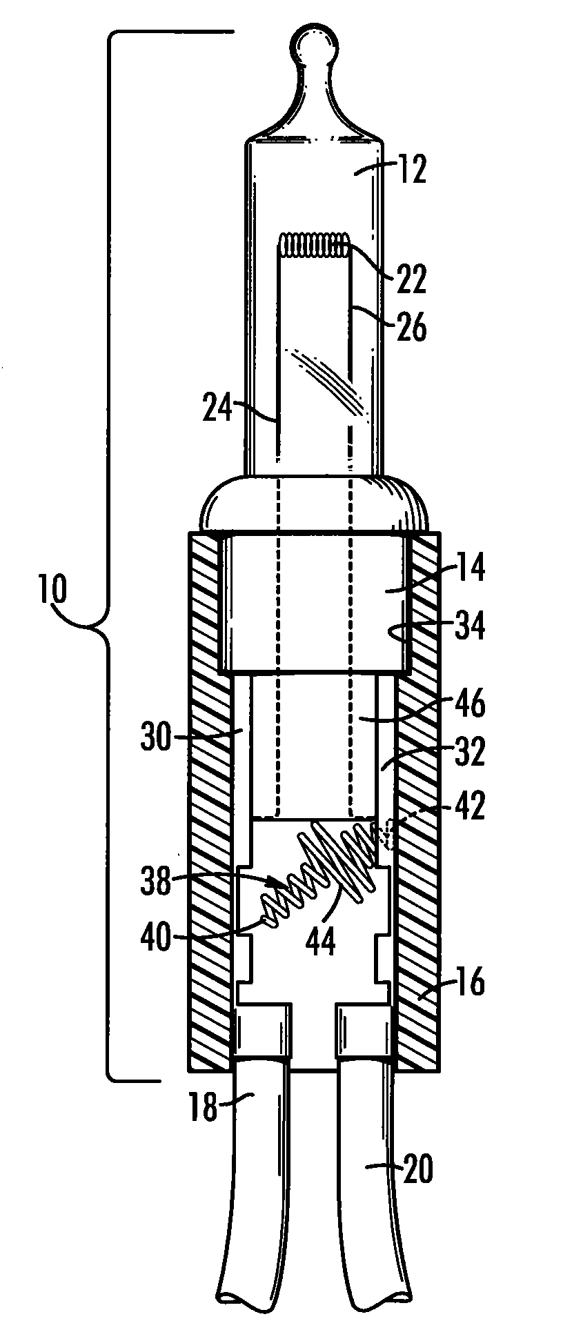
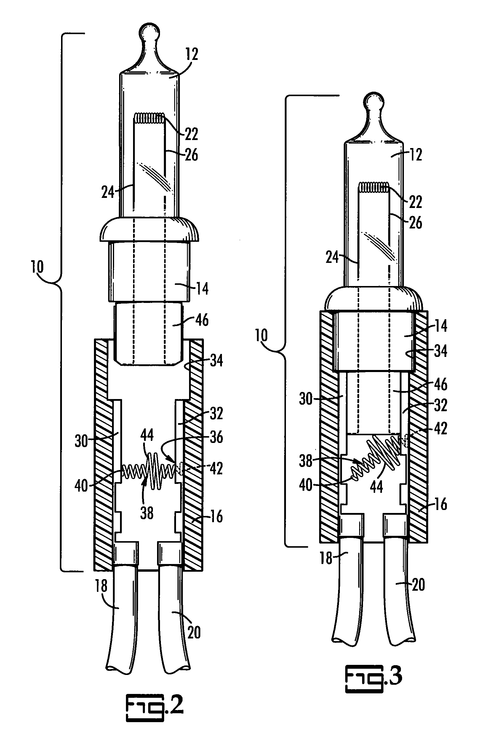
[0022]The present invention is a lamp with a mechanical shunt for use in a string of lights. The shunt, when activated by the removal of the lamp and its holder shifts the flow of the electrical current from a first path leading from electrical terminals in the lamp socket through two Dumet wires to a filament in the bulb, to a second path that bypasses the Dumet wires and filament and flows from the terminals directly through the shunt. The term “light string” refers to plural spaced-apart lamps interconnected in an electrical series by insulated electrical wiring. The term “lamp” refers to the combination of a bulb, holder and socket.

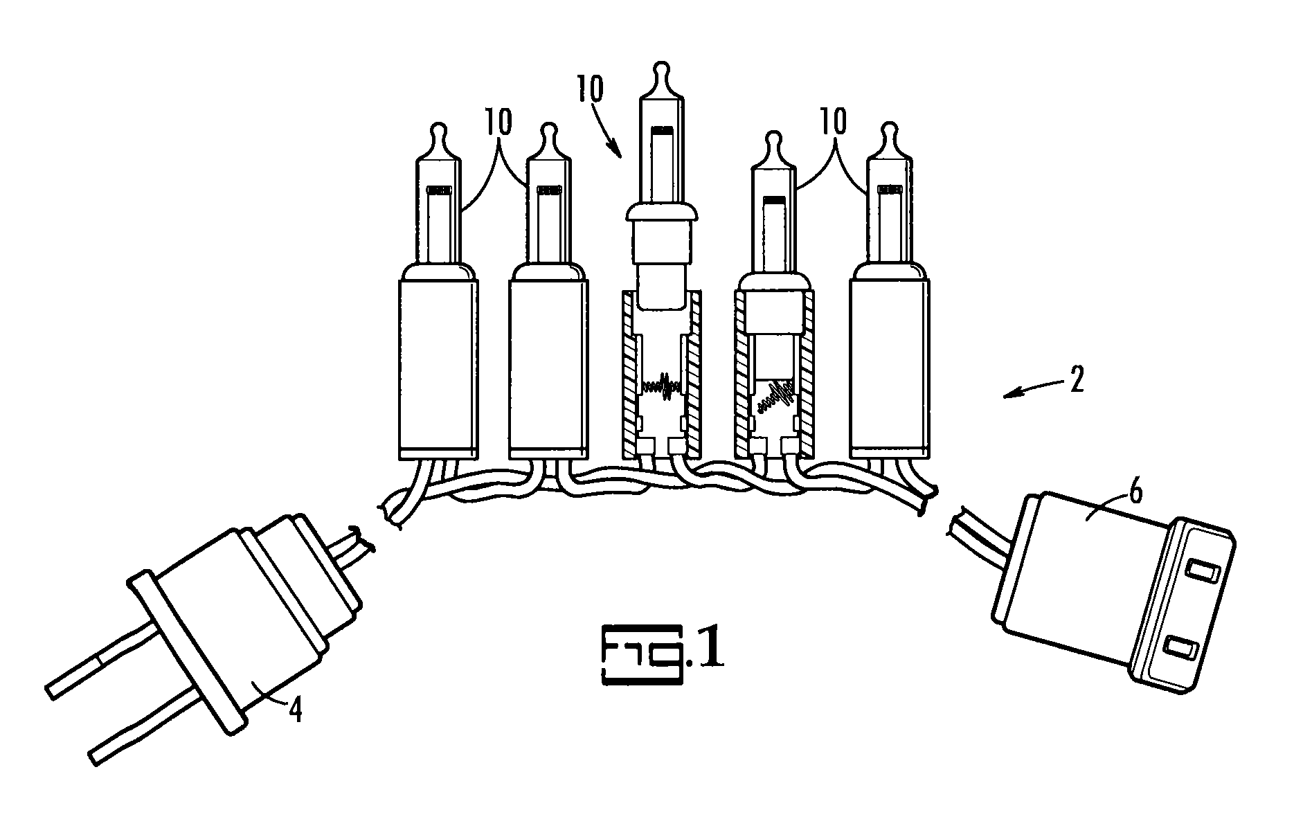
[0023]FIG. 1 illustrates a light string 100 including a plug 4 at one and, a receptacle 300 at the opposing end and plural lamps 10 therebetween all connected in an electrical series by two insulated wires 18, 20. Two lamps 10 are shown partially cutaway to illustrate the present shunt. In one of them a bulb 12 and its holder 14 are removed from a soc...


PUM


Abstract

A mechanical shunt for use in a socket of a string of lights resides in an otherwise typical lamp of a string of lights. The present shunt is a coiled spring shunt held by one of the electrical terminals in the socket so that it is cantilevered toward and in electrical contact with the other electrical terminal. The central portion of the spring shunt has a larger diameter. The lamp holder has bottom that, upon insertion of the holder into the socket, presses down on the central portion of the spring shunt so that its first end is moved out of electrical contact with the first electrical terminal, thereby allowing electrical current to pass through the filament in the bulb.

Description

CROSS REFERENCE TO RELATED PATENTS[0001]The priority benefit of U.S. provisional patent application Ser. No. 61 / 059,914, filed Jun. 9, 2008, which is incorporated herein in its entirety by reference, is claimed. The present application is related to U.S. provisional applications 61 / 058,249 filed Jun. 3, 2008, 61 / 058,248 filed Jun. 3, 2008; and U.S. non-provisional application Ser. Nos. 12 / 133,800 filed Jun. 5, 2008, and 12 / 134,528 filed Jun. 6, 2008, in that all four applications are commonly owned and are directed to related subject matter.BACKGROUND OF THE INVENTION[0002]The present invention relates to light strings such as are used for holiday lighting, and in particular to mechanical shunts for passing electrical current to the next light in the string if the bulb is loose or missing.[0003]Strings of lights are typically wired electrically in series. Consequently, when one light in the string burns out or is removed, all the lights in the string go out. Determining which light ...

Claims


Application Information

Patent Timeline
IPC IPC(8): H01J5/48H01R33/06
CPCF21V19/0005H01R33/96H01R13/7032H01R33/09H01R13/2421F21S4/001F21W2121/00F21S4/10
Inventor GIBBONEY, JR., JAMES W.
Owner EVERSTAR MERCHANDISE
Why Eureka
Try Eureka