Polarization control using diffraction gratings in VCSEL waveguide grating couplers

a technology of vcsel waveguide and diffraction grating, which is applied in the field of coupling light, can solve the problems of imposing restrictions on the array architecture, affecting the beam quality of high power, and the frequency (or wavelength) of light from each vcsel is slightly different and therefore uncorrelated, so as to improve the first polarization mode

Inactive Publication Date: 2009-12-01
OC ACQUISITION CORP
View PDF4 Cites 71 Cited by
  • Summary
  • Abstract
  • Description
  • Claims
  • Application Information

AI Technical Summary

Benefits of technology

[0009]In an embodiment of the present invention, a waveguide grating coupler having first and second mirrors positioned to define a resonant cavity between them is provided. Within such embodiment, a waveguide includes a first grating formed as a part of the waveguide to couple light of a first polarization mode into the waveguide. The waveguide further includes a second grating positioned within the resonant cavity, wherein the second grating is orthogonal to the first grating and so that light coupled to the waveguide is enhanced by reducing light of a second polarization mode, which is different from the first polarization mode.
[0010]In another aspect of the present invention, a waveguide grating coupler having first and second mirrors is provided. Within such embodiment, the first mirror is positioned with respect to the second mirror so that light travels within a resonant cavity defined between the first and second mirrors. A waveguide having a core and cladding is also provided, wherein a first grating is formed as a part of the waveguide and proximate to the waveguide core, and wherein the first grating couples light in a first polarization mode to the waveguide. A second grating, formed as a part of the waveguide and within the cladding, is also provided to create a loss of light in a second polarization mode different from the first polarization mode within the resonant cavity, which results in an enhancement of the first polarization mode.

Problems solved by technology

Coupling of light from one point to another or one location to another presents several challenges, particularly in optical transmission of information, production of high power coherent light, pump sources for lasers, and the like.
However, their beam quality at high power is still poor.
Although the light from each individual VCSEL is coherent, the phase and frequencies (or wavelengths) of the light from each VCSEL are slightly different and therefore uncorrelated.
Both approaches impose restrictions on the array architecture.
More importantly, these existing approaches have had very limited success, even in 1D edge-emitting arrays where both approaches have been extensively investigated.
A further challenge involves coupling light out of a source, such as a VCSEL.
Such coupling may, for example, adversely affect the amount of light which is available to be coupled out of the VCSEL.

Method used


Image

  • Polarization control using diffraction gratings in VCSEL waveguide grating couplers
  • Polarization control using diffraction gratings in VCSEL waveguide grating couplers
  • Polarization control using diffraction gratings in VCSEL waveguide grating couplers

Examples


Embodiment Construction

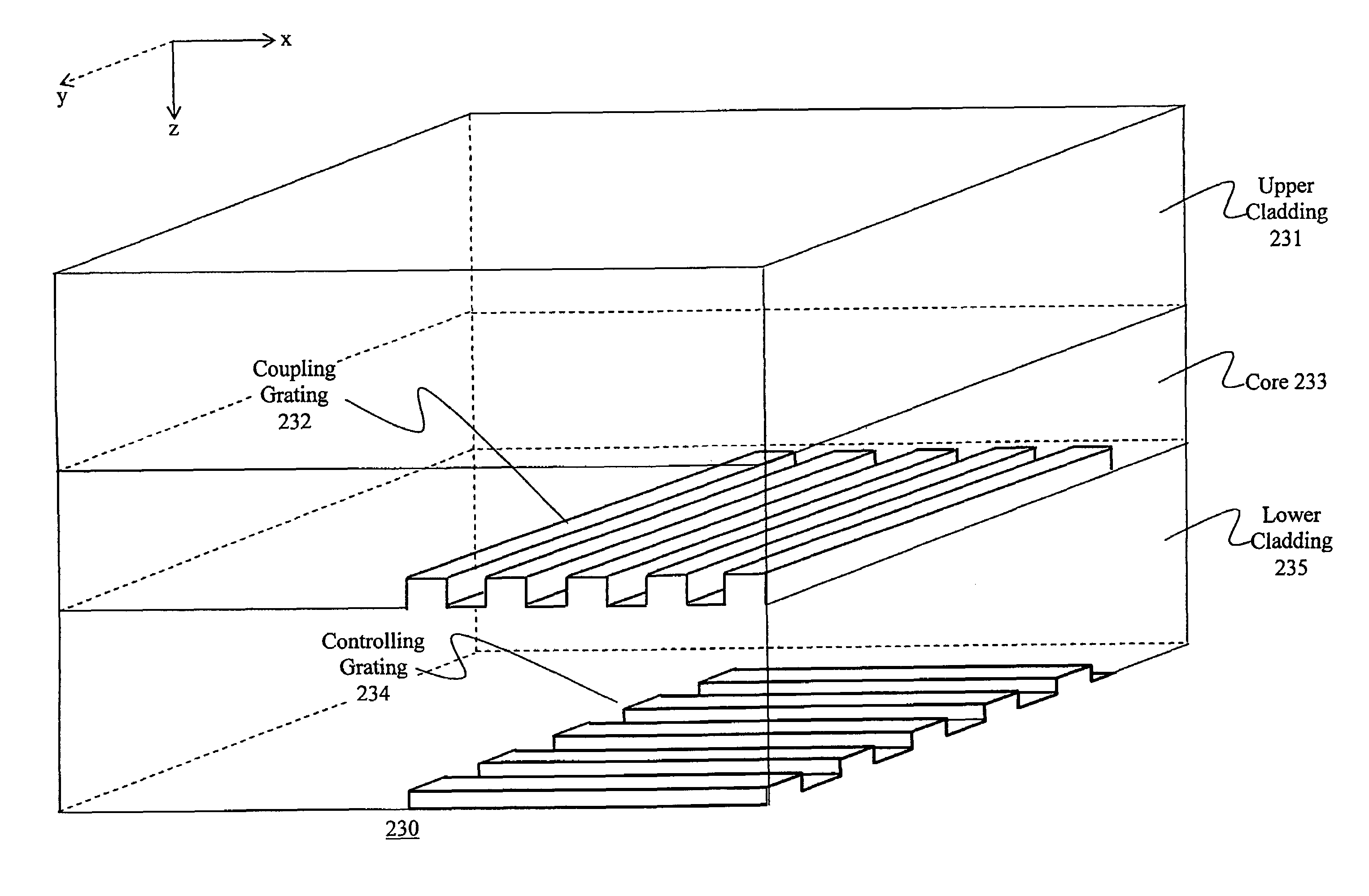
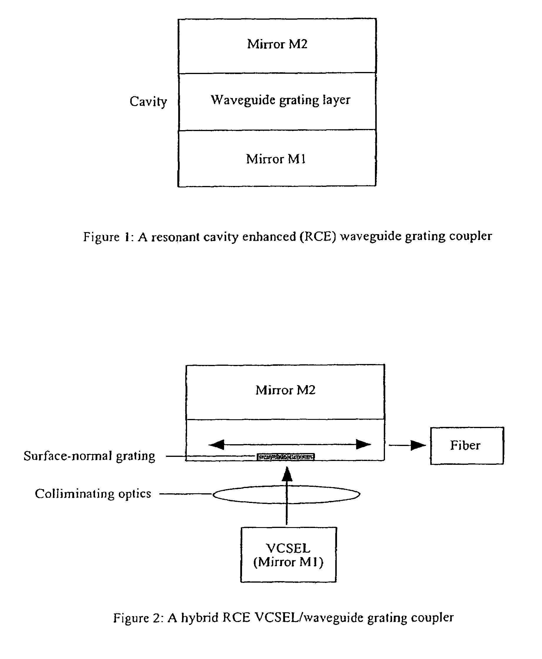
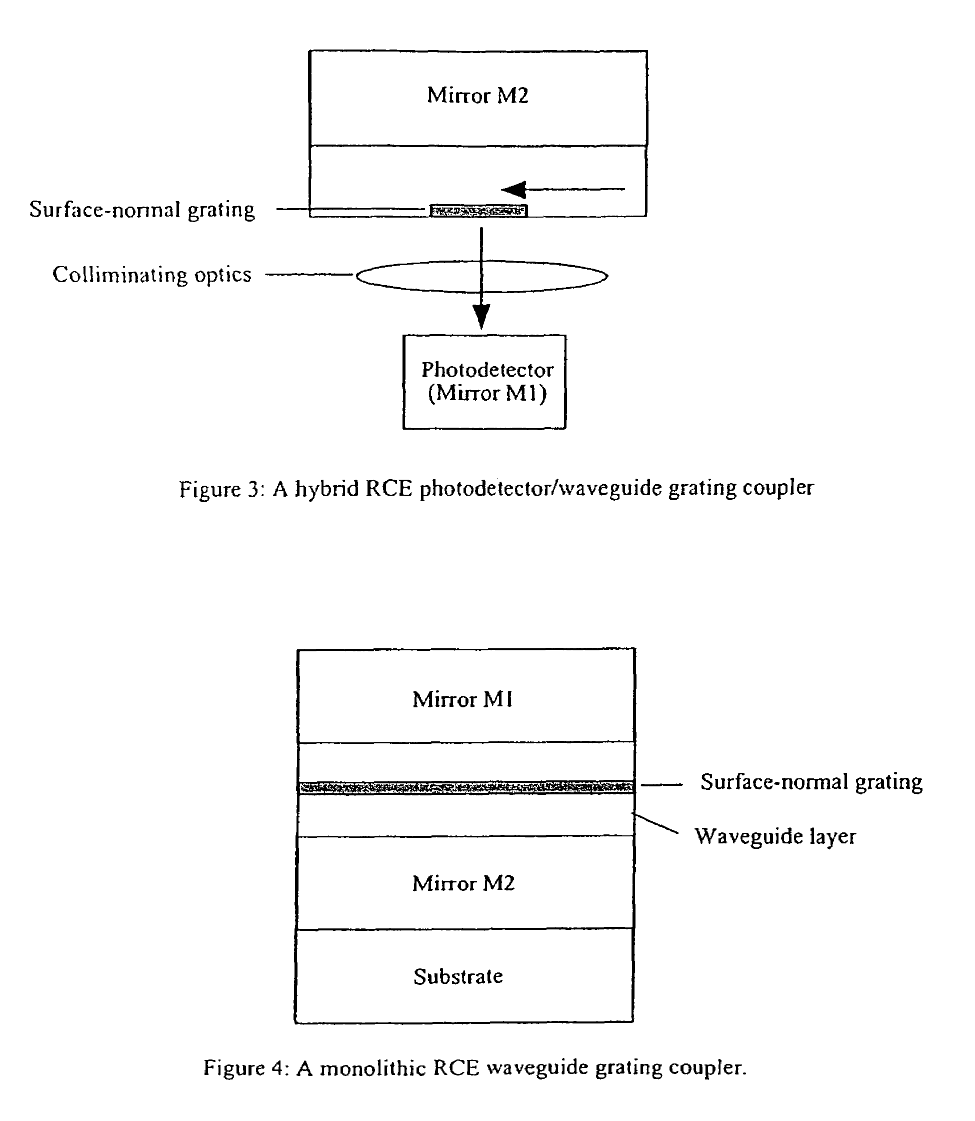
[0096]A resonant cavity enhanced (RCE) waveguide grating coupler includes a surface-normal waveguide grating inserted into a Fabry-Perot cavity (FIG. 1). The Fabry-Perot cavity has two mirrors and, between them, a cavity which contains a waveguide grating layer. The mirror can be either a semiconductor layer, a semiconductor distributed bragg reflector (DBR) or a dielectric DBR. Semiconductor DBR mirrors can be a part of an optoelectronic device, particularly a vertical cavity surface emitting laser (VCSEL) or a photodetector. The thickness of the cavity should be designed in such a way that a phase matching condition is satisfied, for resonance. Light can be coupled into / out of an optical fiber through the surface-normal waveguide grating. A coupling efficiency into the waveguide layer can be greatly enhanced due to the large increase of the resonant optical field introduced by the Fabry-Perot cavity. Two approaches can be used to realize the RCE waveguide grating coupler: hybrid a...


PUM


Abstract

A VCSEL waveguide grating coupler is provided such that a first and second mirror are positioned to define a resonant cavity between them. The waveguide grating coupler further includes a waveguide having a first grating formed as a part of the waveguide to couple light of a first polarization mode into the waveguide. A second grating is formed on the waveguide grating coupler and is orthogonal to the first grating. The second grating is operative to enhance the light coupled to the waveguide by creating a loss difference between light of the first polarization mode and light of a second polarization mode, so that light of the first polarization mode lases preferentially within the VCSEL.

Description

RELATED APPLICATIONS[0001]The present application is a Continuation-in-Part of U.S. patent application Ser. No. 10 / 860,607, filed Jun. 3, 2004, now U.S. Pat. No. 7,535,944, which is a Continuation-in-Part of U.S. patent application Ser. No. 10 / 136,953, filed May 1, 2002, now U.S. Pat. No. 6,829,286, which is a continuation of U.S. patent application Ser. No. 09 / 867,719, filed May 29, 2001, now abandoned, which claims priority under 35 U.S.C. §119(e) from provisional application No. 60 / 207,525, filed May 26, 2000.GOVERNMENT INTERESTS[0002]The United States Government has a paid-up license in this invention and the right in limited circumstances to require the patent owner to license others on reasonable terms as provided by the terms of Contract No. F29601-03-C-0074 awarded by the United States Air Force Research Laboratory.TECHNICAL FIELD[0003]The present invention is directed generally to coupling light from one location to another, and more particularly to efficiently coupling lig...

Claims


Application Information

Patent Timeline
Patent Type & Authority Patents(United States)
IPC IPC(8): H01S3/08
CPCG02B6/4214H01S5/1032H01S5/423H01S5/18355G02B6/2793H01S5/141H01S5/1838H01S5/187H01S5/4012H01S5/026
Inventor GUILFOYLE, PETERLOUDERBACK, DUANEPETAL, KETANMAHNKOPF, SVEN
Owner OC ACQUISITION CORP
Why Eureka
Try Eureka