

Drum brake apparatuses
a drum brake and apparatus technology, applied in the direction of fluid actuated drum brakes, hydraulic brakes, hoisting equipment, etc., can solve the problems of insufficient braking effect of various brakes, inconvenient operation of drum brakes, and reduced effectiveness of drum brakes, so as to improve the braking distance
- Summary
- Abstract
- Description
- Claims
- Application Information
AI Technical Summary
Benefits of technology
Problems solved by technology
Method used
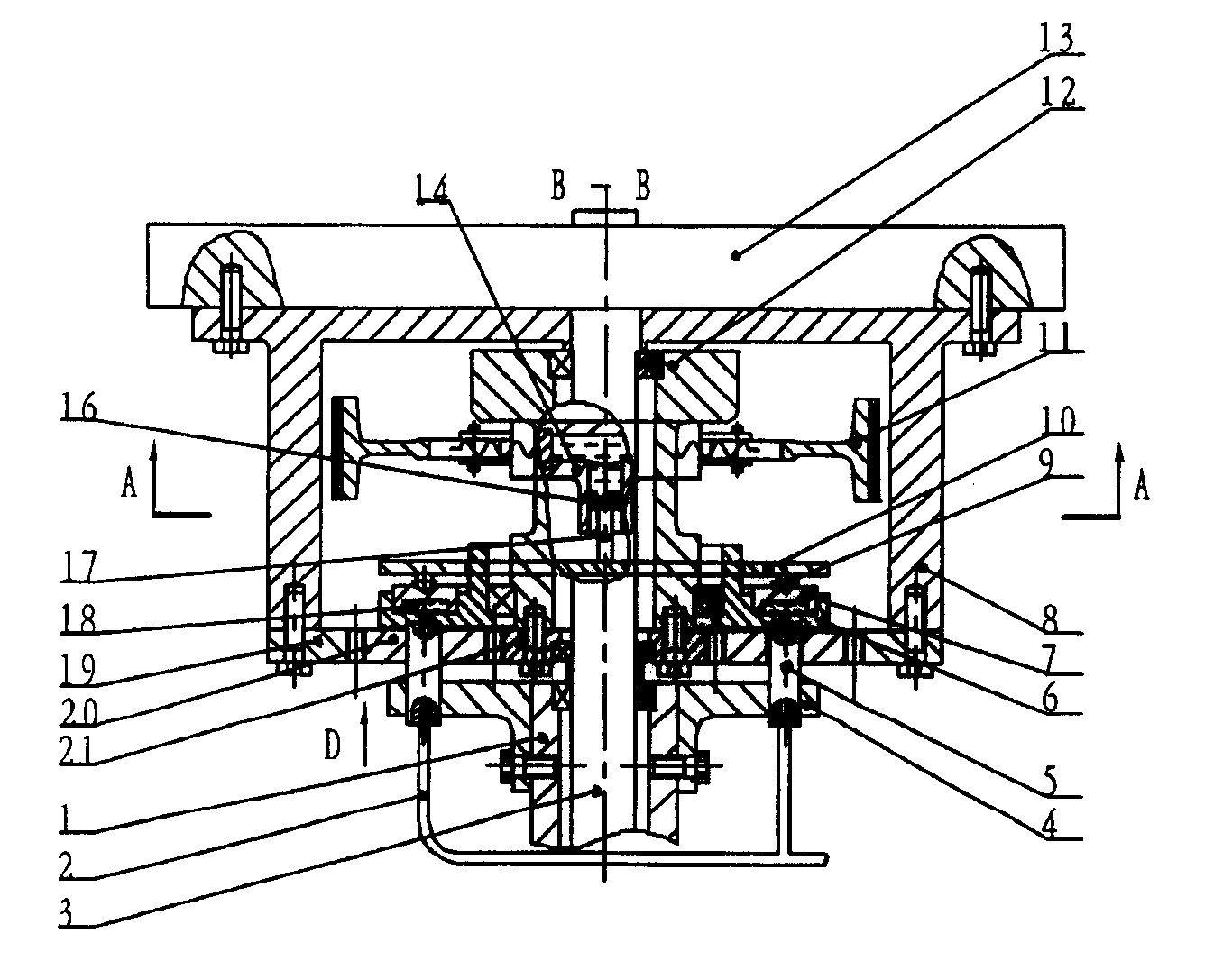
Image

Examples
Embodiment Construction
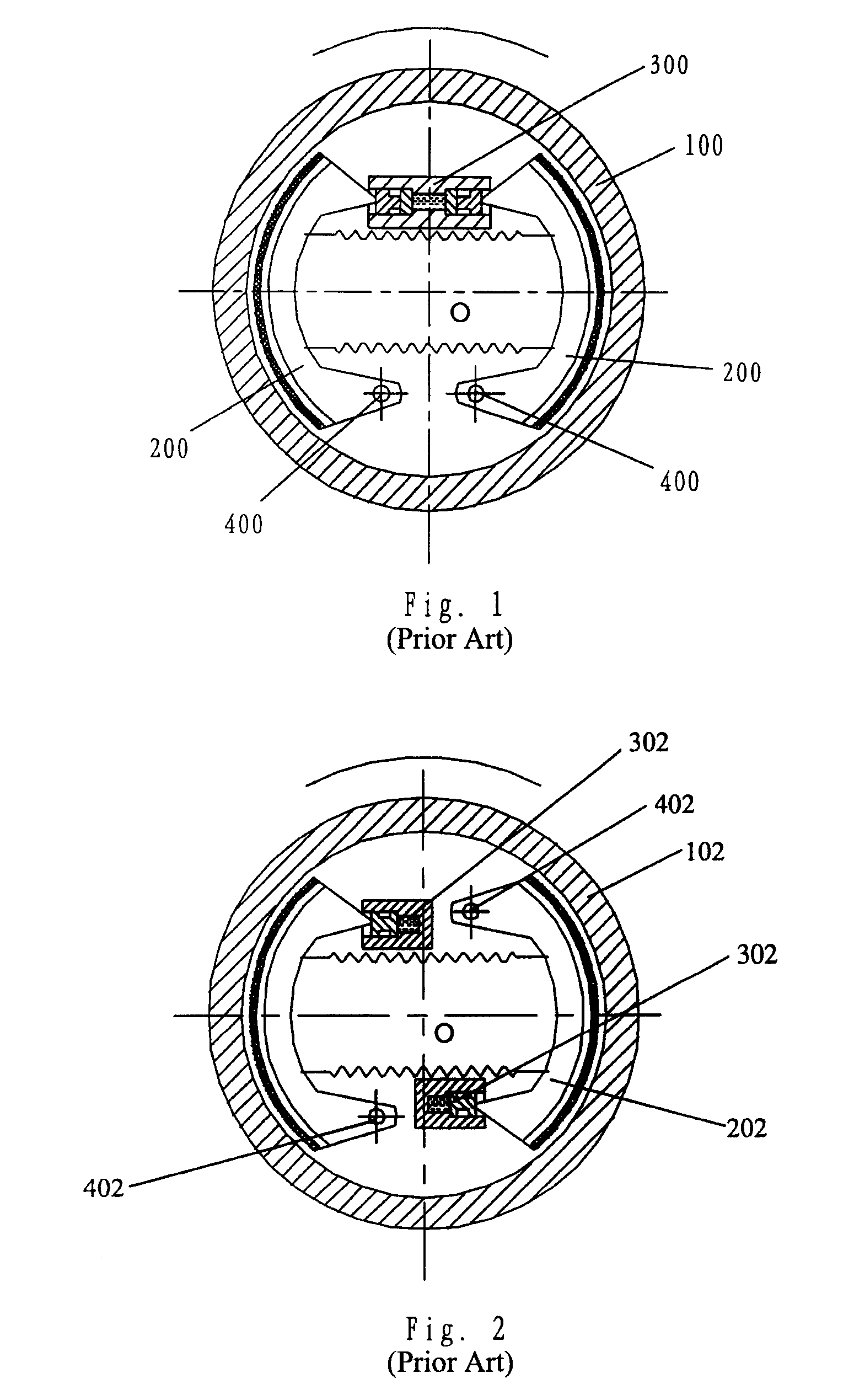
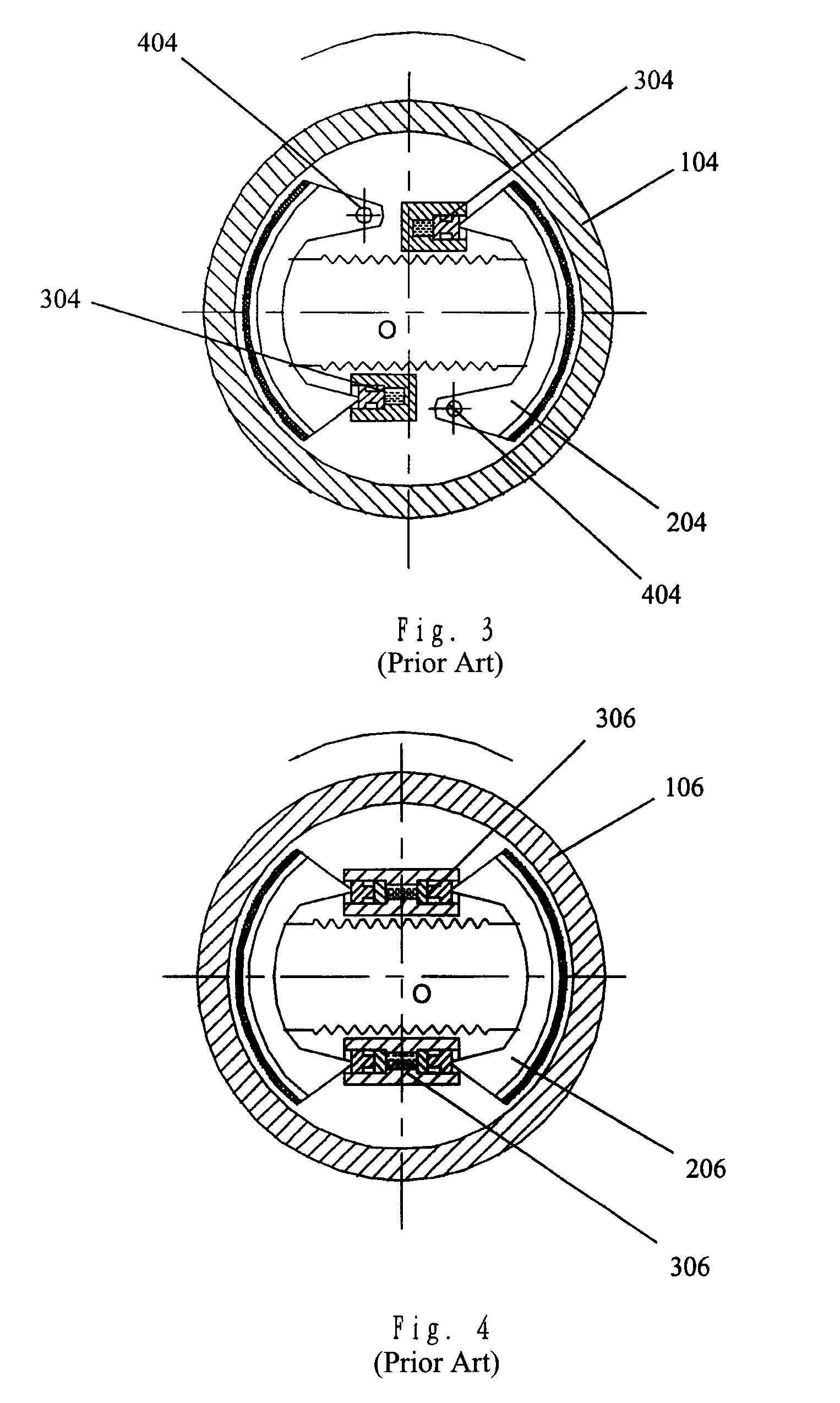
[0028]As discussed in the background section, the prior art drum brakes operate by creating friction between a fixed component and a moving component. From the energy point of view, the braking process is a process where, through friction, the mechanical energy of the automobile is converted into heat energy and expanded. When the automobile brake is applied, the friction between the brake shoes and the brake drum creates heat energy, and the amount of the heat energy equals the mechanical energy converted in the process. The more mechanical energy is converted during a given time period, the less braking time and distance is required to stop an automobile. The fundamental reason is that the absolute value of the speed reduced during the braking period has been increased. In other words, given the same braking force, friction factor of the friction pads of the brake shoes and the typical dimensions for the typical brakes, if by changing the brake structure that the consumption of th...
PUM
 Abstract
Description
Claims
Application Information