Radiation imaging apparatus

a radiation imaging and apparatus technology, applied in the field can solve the problems of increasing not always meeting the requirements of a medical site at present, and burdening medical institutions with a heavy cost, so as to reduce the cost of radiation imaging apparatus and burden medical institutions with cos

Active Publication Date: 2009-12-08
CANON KK
View PDF36 Cites 40 Cited by
  • Summary
  • Abstract
  • Description
  • Claims
  • Application Information

AI Technical Summary

Benefits of technology

[0008]Furthermore, a radiation imaging apparatus of the present invention includes a flat panel detector which derives a radiation image according to incident radiation, a holding unit which holds the flat panel detector and a connecting mechanism capable of performing a connecting and disconnecting between the holding unit and the flat panel detector, where the flat panel detector can be controlled so that the maximum number of images derived by a continuous radiography that the flat panel detector can perform in a state where the flat panel detector is disengaged from the holding unit is smaller than the maximum number of images derived by the continuous radiography that the flat panel detector can perform in a state where the flat panel detector is held by the holding unit.
[0010]The present invention enables performing plain radiography and short-time fluoroscopic radiography with a flat panel detector removed from the holding unit and providing the radiation imaging apparatus capable of handling various radiographic modes with portability, which is a feature of the flat panel detector, maintained. In addition, various radiographic modes can be handled by a single flat panel detector, which can suppress increase in cost of the radiation imaging apparatus and burden to medical institutions with cost.

Problems solved by technology

As previously described, the radiation imaging apparatus using the flat panel detector has advantages over a conventional radiation imaging apparatus using I.I.; however it does not always sufficiently meet requirements in a medical site at present.
However, the preparation of a plurality of flat panel detectors for each such type of radiography may increase the cost of a radiation imaging apparatus and burden medical institutions with a heavy cost.
Furthermore, operation controls suited for respective flat panel detectors are required, which may complicate the operation controls of the radiation imaging apparatus.

Method used


Image

  • Radiation imaging apparatus
  • Radiation imaging apparatus
  • Radiation imaging apparatus

Examples


first embodiment

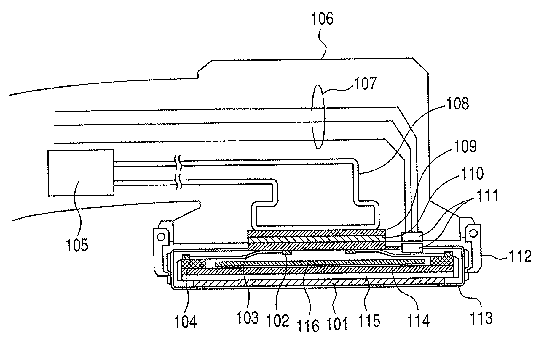
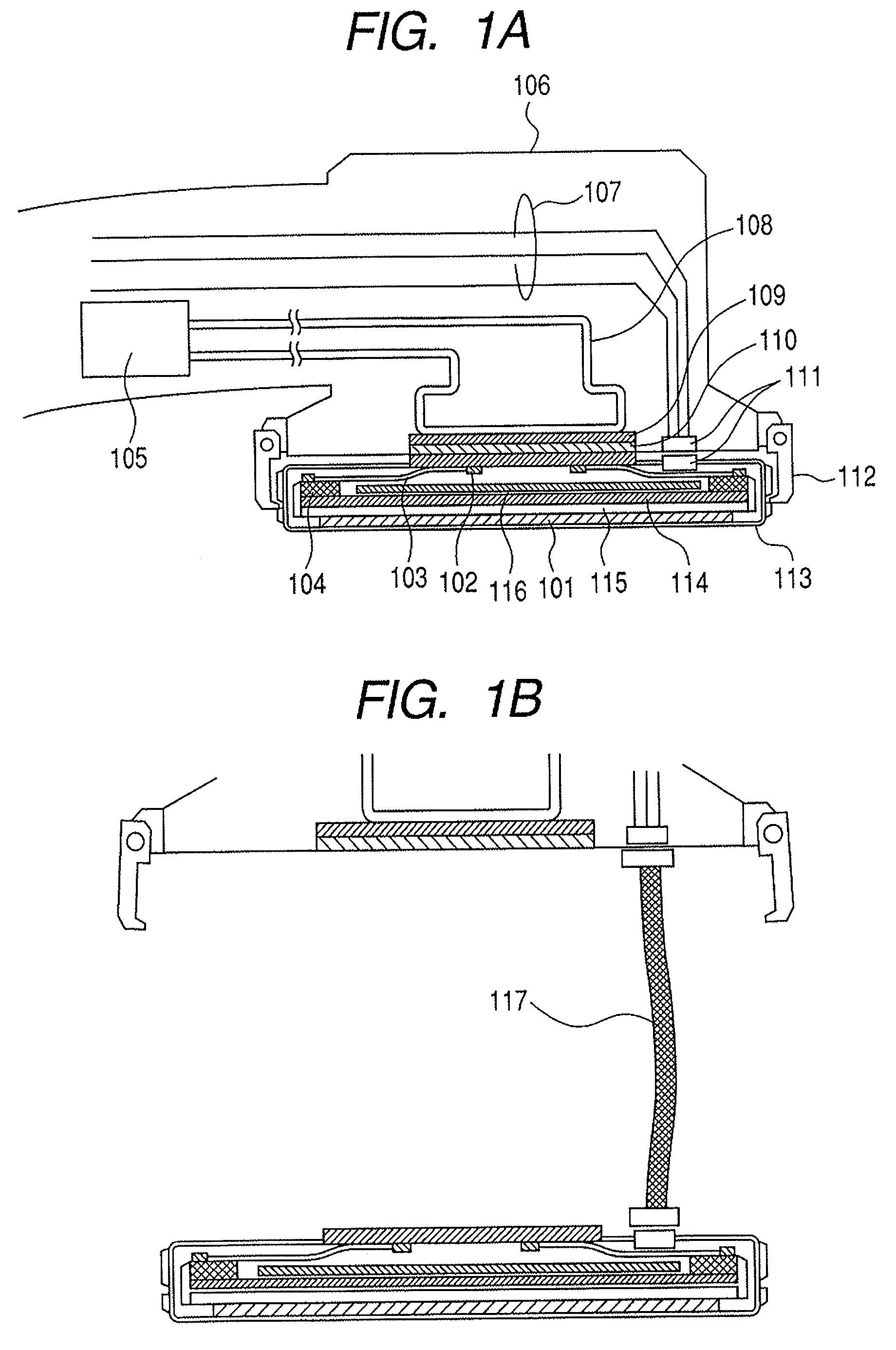
[0033]The first embodiment of the present invention is described in detail with reference to FIGS. 1A and 1B. FIGS. 1A and 1B are enlarged cross-sections of a flat panel detector and a holding unit in the radiation imaging apparatus of the present invention. FIG. 1A is a cross-section illustrated with the flat panel detector fixed to the holding unit. FIG. 1B is a cross-section illustrated with the flat panel detector removed from the holding unit.

[0034]In FIGS. 1A and 1B, reference numeral 101 denotes a scintillator; 102, a first thermal diffusion plate; 103, a first heat pipe; 104, a signal processing circuit; 105, a cooling mechanism; 106, a C-type arm being a holding unit; 107, an electric wiring; 108, a second heat pipe; and 109, a second thermal diffusion plate. Reference numeral 110 indicates a thermal conduction plate; 111, a connector being an electric connecting unit; 112, a fixing hook being a mechanical connecting unit; 113, a housing; 114, a support base; 115, a sensor ...

second embodiment

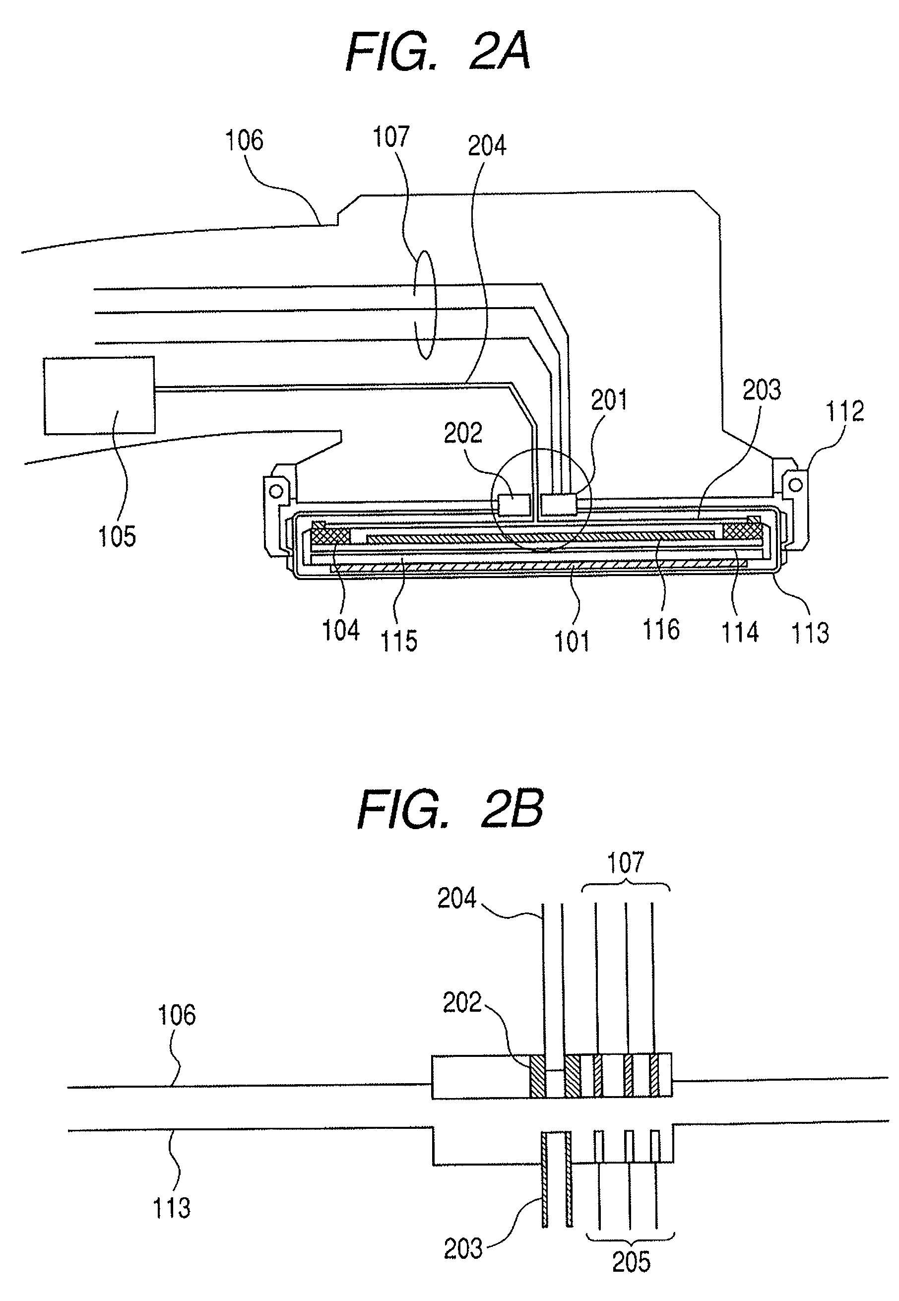
[0039]The second embodiment of the present invention is described in detail with reference to FIGS. 2A and 2B. FIGS. 2A and 2B are enlarged cross-sections of a flat panel detector and a holding unit in the radiation imaging apparatus of the present invention. FIG. 2A is a cross section illustrated with the flat panel detector fixed to the holding unit. FIG. 2B is a cross-section illustrated with the flat panel detector removed from the holding unit. Incidentally, the same reference numerals are used for the same composing elements as in the first embodiment to omit the detailed descriptions thereof.

[0040]Reference numeral 201 represents a connector electrically connecting the flat panel detector to the electric wiring 107 provided on the C-type arm 106. Reference numeral 202 denotes a fitting of metal such as copper high in heat conductivity which is so configured as to bring a first heat pipe 203 into contact with a second heat pipe 204 to conduct heat from the first heat pipe 203 ...

third embodiment

[0043]The third embodiment of the present invention is described in detail with reference to FIGS. 3 to 5C. FIG. 3 is a cross section illustrated with the flat panel detector fixed to the holding unit. FIG. 4A is a schematic perspective view illustrating the connecting mechanism of the flat panel detector and FIG. 4B is a schematic perspective view illustrating the connecting mechanism of the holding unit. FIGS. 5A, 5B and 5C are schematic perspective views illustrating a method of connecting the flat panel detector to the holding unit. Incidentally, the same reference numerals are used for the same composing elements as in the first or the second embodiment to omit the detailed descriptions thereof.

[0044]In the present embodiment, mechanical, electric and thermal connections are made using a first connecting mechanism provided on the flat panel detector and a second connecting mechanism provided on the C-type arm 106 that serves as a holding unit. Reference numeral 301 denotes a fl...


PUM


Abstract

A single flat panel detector provides radiation images which can correspond with various radiographic modes. In a radiation imaging apparatus including a flat panel detector which derives a radiation image according to incident radiation, a holding unit which holds the flat panel detector and a connecting mechanism capable of performing a connecting and a disconnecting between the holding unit and the flat panel detector, the flat panel detector can be controlled so that the maximum number of radiation images that the flat panel detector can derive when the flat panel detector is disengaged from the holding unit is smaller than the maximum number of radiation images that the flat panel detector can derive when the flat panel detector is held by the holding unit.

Description

TECHNICAL FIELD[0001]The present invention relates to a radiation imaging apparatus suited for use in medical diagnosis, for example, and in particular, to a radiation imaging apparatus including a flat panel detector using a semiconductor element as a detector. In the present invention, the term “radiation” includes not only α rays, β rays and γ rays which are beams of particles (including photons) emitted by radioactive decay, but also beams having energy higher than or comparable to that of those rays, for example, X-rays, particle beams, cosmic rays and others.BACKGROUND ART[0002]Hitherto, an image intensifier (hereinafter, abbreviated to I.I.) has been used as a detector for capturing radiation images in a radiation imaging apparatus for medical diagnosis for use in fluoroscopic radiography. The radiation imaging apparatus using I.I. performs fluoroscopic radiography in such a manner that radiation image information based on radiation that has passed through an object is conver...

Claims


Application Information

Patent Timeline
Patent Type & Authority Patents(United States)
IPC IPC(8): G01T1/20G03B42/04
CPCA61B6/4233A61B6/4429A61B6/4488A61B6/4411A61B6/4405A61B6/56A61B6/4441
Inventor YAGI, TOMOYUKIENDO, TADAOKAMESHIMA, TOSHIOTAKENAKA, KATSUROYOKOYAMA, KEIGO
Owner CANON KK
Why Eureka
Try Eureka