Arrayed multi-fiber connector

a multi-fiber connector and connector technology, applied in the field of optical fiber coupling, can solve the problems of insertion loss, aberration and irregularity, and no perfect connector exists

Active Publication Date: 2009-12-08
MEGLADON MFG GROUP
View PDF22 Cites 28 Cited by
  • Summary
  • Abstract
  • Description
  • Claims
  • Application Information

AI Technical Summary

Benefits of technology

[0002]Fiber optics are long, thin strands of very pure glass or other materials about the diameter of a human hair used to transmit light. Each strand of optical fiber generally has three components, a core, cladding, and a buffer coating or jacket. The core is a thin glass center of the fiber where the light travels. The cladding is the outer optical material surrounding the core that reflects the light back into the core. The buffer coating is a plastic coating that protects the fiber from damage and moisture. Generally, fiber optic strands can be arranged in bundles called optical cables and used to transmit light signals over long distances.

Problems solved by technology

Insertion loss occurs when the optical energy from one fiber is not properly inserted into the receiving fiber, and can result from such things as variations in fibers, misalignment of the fibers, and optical aberrations and irregularities at the ends of the sending and receiving fibers.
Of course, no perfect connector exists, and limitations on their effectiveness are imposed by such considerations as variations in the fibers themselves, tolerances of the connectors or splices, cost of production, and ease of use.
This misalignment of the core can cause insertion loss, as the fiber to which this example may be joined would probably not have an identical misaligned core.
The misalignments between the sending and receiving core allow light to impinge on the cladding instead of the core, causing insertion loss.
Light in the transmitting core thus impinges on the receiving fiber outside its core, and this results in loss.
However, fabricating and positioning microlenses can be a time consuming and expensive process.
This can cause loss as the diverging light from the transmitting fiber expands to impinge on an area greater than the core of the receiving fiber.
The farther the two fiber cores are apart, the greater likelihood of loss.
In this case, light emitted from one fiber will only partially transition into the core of the receiving fiber, resulting in loss.
Again, this causes some loss as not all the light from the transmitting fiber transitions into the core of the receiving fiber.
Though microlenses are capable of reducing loss in fiber optic connections, they are difficult to fabricate and properly align and attach to fiber ends.
Further, microlenses cannot fully solve the problems, as aberrations on the ends of, for example, a poorly cleaved fiber, may cause light to diverge even outside the width of the lens.
Materials like plastics may not hold a tolerance and cause misalignment of the fibers.
This problem is increased by the fiber related and mechanical related issues described above.

Method used


Image

  • Arrayed multi-fiber connector
  • Arrayed multi-fiber connector
  • Arrayed multi-fiber connector

Examples


Embodiment Construction

[0034]The numerous innovative teachings of the present application will be described with particular reference to the presently preferred embodiment (by way of example, and not of limitation).

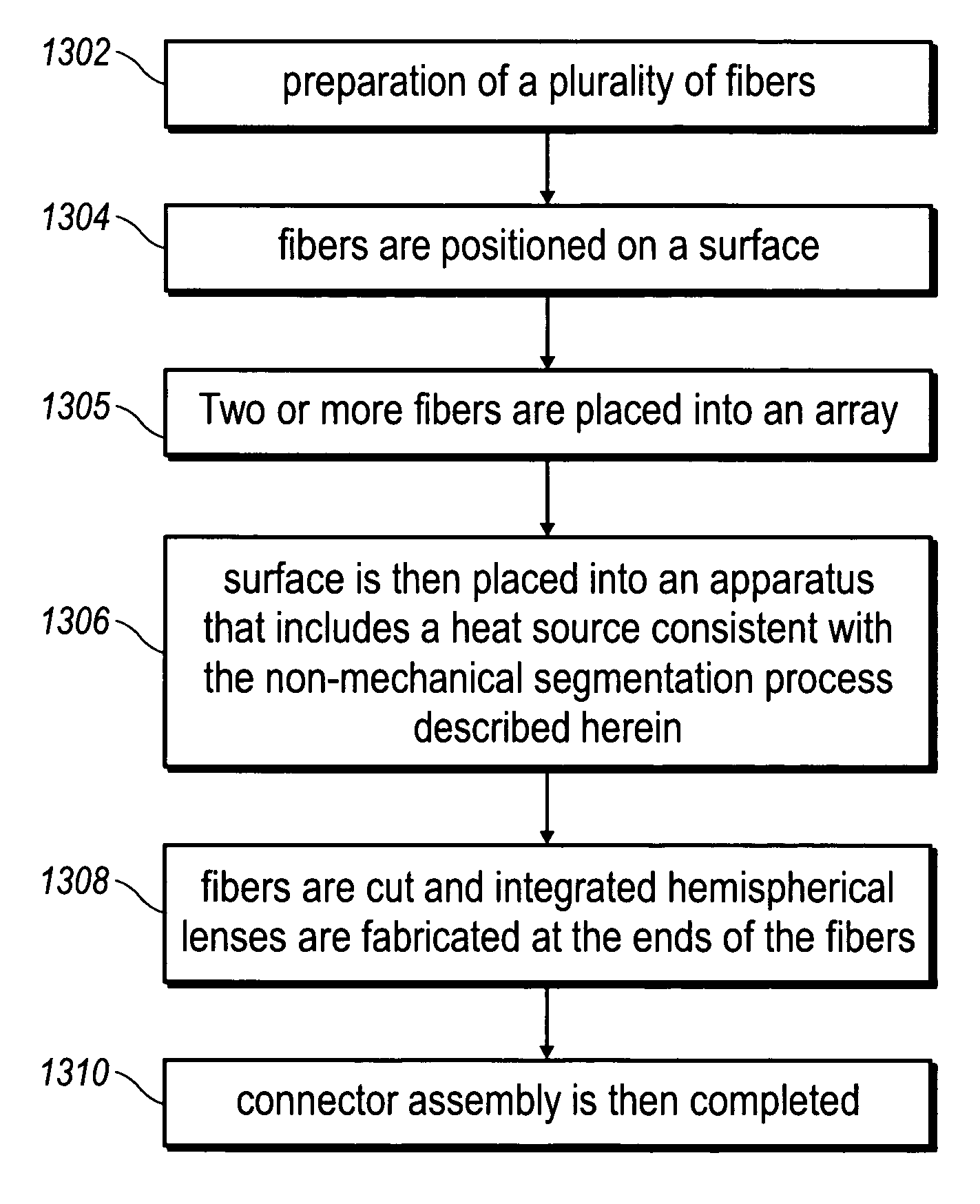
[0035]In a preferred embodiment, the present innovations are implemented in the context of an array of optical fibers assembled as part of an optical connector apparatus. The optical fibers are preferably assembled into the arrays as described below, and then lenses are formed on the optical fibers using, for example, an energy source, preferably a laser (however, this order can be varied within the scope of the present innovations). These and other innovative aspects are described below.

[0036]FIG. 5 shows a pair of fiber ends 502, 504 with integrated hemispherical lenses 506, 508 formed on each of the fiber ends 502, 504. In this example, lens 506 focuses light from fiber 502 into fiber 504 through lens 508. In a preferred embodiment, the lenses are shaped using a method that shapes the optica...


PUM


Abstract

A system and method for segmenting a plurality of optical fibers to form an arrayed multi-fiber optical connector. In one example embodiment, the present innovations include an optical connector that has a plurality of optical fibers arranged into a two-dimensional array, the optical fibers being segmented by a laser emitting substantially in the infra-red spectrum. The optical fibers are preferably segmented after having been positioned on a substrate that becomes part of the connector.

Description

FIELD OF THE INVENTION[0001]The present inventions relate generally to coupling of optical fibers, and more specifically to coupling multiple optical fibers using a thermal shaping process.BACKGROUND AND SUMMARY OF THE INVENTION[0002]Fiber optics are long, thin strands of very pure glass or other materials about the diameter of a human hair used to transmit light. Each strand of optical fiber generally has three components, a core, cladding, and a buffer coating or jacket. The core is a thin glass center of the fiber where the light travels. The cladding is the outer optical material surrounding the core that reflects the light back into the core. The buffer coating is a plastic coating that protects the fiber from damage and moisture. Generally, fiber optic strands can be arranged in bundles called optical cables and used to transmit light signals over long distances.[0003]Fiber optic communication channels are widely used in communication systems around the world. When constructin...

Claims


Application Information

Patent Timeline
Patent Type & Authority Patents(United States)
IPC IPC(8): G02B6/00
CPCG02B6/262G02B6/3885G02B6/3833G02B6/3853G02B6/3676G02B6/3672
Inventor MAYS, JR., ROBERTCULBERT, JOHN M.
Owner MEGLADON MFG GROUP
Why Eureka
Try Eureka