The problem is more complicated for trucks, enclosed farm tractors and construction equipment that not only can have much larger blind spots along the sides of the vehicle but also can have a serious
blind spot starting in front of the right front bumper of the vehicle and extending beyond the right door.
This
blind spot is particularly serious with trucks and even vans, SUVs and cars in urban driving where small vehicles, motorcycles, pedestrians, bicycles etc. in this area can be completely hidden from the view of the driver.
This is difficult to do without knowledge of the location of the eyes of the driver.
For most systems that do not incorporate an occupant sensor capable of determining the location of the driver's eyes, there is a risk that the mirrors will be positioned wrongly thus exacerbating rather than helping the
blind spot detection problem.
Also, a system that rotates the mirror will make the driver nervous since he or she will not be able to see the scene that he or she is accustomed to seeing in the mirror.
Monitoring systems that are based on
radar or
ultrasound have been available but not widely adopted for automobile
blind spot detection for reasons related to cost, accuracy and false alarms.
Both systems use beams of energy that can become several feet in
diameter by the time they reach the edges of the blind spot and thus can confuse a large vehicle or a guardrail, sign, parked car etc. two lanes over with a vehicle in the blind spot.
A tradeoff exists in all such systems where, if all threatening objects are made known to the driver, the
false alarm rate becomes unacceptable and the driver soon loses confidence in the system and ignores it.
These prior art systems thus have serious failure
modes.
Some other problems arise when a vehicle strays into the lane of the host vehicle, i.e., the vehicle with the blind spot
detector.
Most systems will fail to warn the operator and thus an accident can result.
As such, the blind spot problem is really two problems relating to the motion of the potentially striking vehicle and the potentially struck vehicle.
A problem that is addressed herein is to determine what information is needed about the object in the blind spot and then the manner in which this information is presented to the vehicle operator so as to eliminate accidents caused by the failure of the operator to see such an object.
This system must work with very high reliability and accuracy since the consequences of an error can be serious injuries or death.
The CMU solution, based on observations without the aid of location determining technologies such as DGPS and accurate maps, will require reliance on models of vehicles, models of pedestrians and human factors, the analysis of all of which is at best inexact and incapable of solving the problem of collision avoidance.
Also, by not having a good identification of such objects, such as provided herein, the CMU solution will not be able to provide the proper response in critical situations.
Radar in general has a high
false alarm rate due to the large pixel size at any significant distance from the host vehicle, to multipath effects and reflections from signs, bridges, guardrails etc.
However, for imaging applications, the
slow speed and relatively large pixel size renders ultrasonics marginal even for
close up targets.
Also, ultrasonic waves can be significantly distorted by thermal gradients and wind.
Its limitations are its sensitivity to environmental conditions.
Despite its high cost, this technique offers the advantages of being insensitive to environmental conditions, but the
disadvantage of having a large pixel size.
It also has the
disadvantage of having a large pixel size resulting in a high
false alarm rate and too little information to permit object identification.
Poor resolution compared to other techniques makes it unlikely that these devices will be used for
blind spot detection since most objects are close to the vehicle.
However, these references do not disclose a camera and in fact, each
receiver is a
single pixel device.
Otherwise, they do not provide accurate
ranging.
No direct measurement of the distance is achieved, however, in some cases multiple detectors are used in such a way that when the adjacent detected vehicle is very close to the
detector, that is, below the threshold distance, the sensing of the adjacent vehicle is suppressed.
The locations of the antenna, however, make it difficult to detect many objects in the side blind spots.
The particular location and velocity of such objects are also not accurately determined.
The device is based on a
single pixel having a relatively
large size making recognition and identification of the object impossible.
This is a
single pixel device and thus no imaging or object recognition is possible.
Thus, no accurate range measurement is provided.
Additionally, it provides too much information for the driver thus creating the possibility of driver
information overload.
The main problem is that the LCD driver-viewing screen is more likely to confuse than to aid the driver due to its poor dynamic
light intensity range and the ability to relate the image to the location and velocity of the object in the blind spot.
It requires multiple locations and cannot be mounted, for example, on the side rearview mirror.
As a result, many objects, such as a high speed passing vehicle, are missed.
It invariably will miss objects that move rapidly into blind spot.
It does not appear that the system can be easily adjusted for vehicles of different length.
The problems are that no attempt is made to analyze the image or to determine its velocity and therefore, a high false alarm rate can be expected.
However, the system does not provide an image and therefore no optical pattern recognition is possible.
The 10-degree
divergence angle of
radar indicates that a single pixel has a
diameter of over 3 feet at 20 feet from the
radar transmitter, which is insufficient resolution to determine the lane that the threatening vehicle is occupying, especially if there is a slight curvature in the road.
Such a system is not sufficiently accurate to provide drivers who are attempting to merge into adjacent lanes with sufficiently accurate position information to permit a safe merge under
heavy traffic without
visual contact.
Additionally, there is no pattern recognition claimed or even possible with this
low resolution device.
Some problems are that this system will interfere with other vehicles having the same system.
Once again, the system will invariably miss a high-speed vehicle passing on either the right or the left since it is limited to a two
mile per hour velocity difference between the blind spot object and the host vehicle.
It also appears to be a very expensive system.
Another potential problem is that when an especially long
truck having the system of this patent is turning, the system would pick up the end of
truck and treat it as an object in the blind spot.
One problem with this device is that this system does not know where the
infrared rays are coming from.
This is an alternate method of discriminating between a vehicle and the road but one that still lacks resolution.
Unfortunately, the various figures in the patent that illustrate this phenomenon are not accurate and appear to show that the positions of the vehicles relative to the subject vehicle can be visually seen which is not the case.
Also, no attempt has been made to identify and analyze objects in the blind spot and warn the driver of a pending accident.
The CCD array suffers from the problem that, due to its limited
dynamic range, it can be overwhelmed by light from the sun, for example, reflected off a vehicle or other surface.
In other words, the system knows that something is in the blind spot but does not know what it is or even accurately where it is.
There is no accurate
ranging and there will likely be a high false alarm rate with this system.
It is a one-pixel device and therefore does not permit the location of the object in the blind spot to be determined.
This device and other similar passive
infrared devices will have trouble distinguishing between a small objects such as a motorcycle which is relatively close to the sensor and larger objects such as a
truck which are relatively far away, for example two lanes over.
It does not attempt to capture an image of an object in the blind spot or determine the identity of such an object and thus many non-threatening objects will appear to be threatening.
Accordingly, the system can be expected to have a high false alarm rate.
As a result, such systems miss a high-speed vehicle that is in the blind spot and was not observed approaching the blind spot by the driver.
Thus, none of the related art described above discloses a method or apparatus of monitoring the area surrounding a vehicle that analyzes an image of one or more objects that occupy the blind spot, identifying them and determining the location and
relative velocity of the objects relative to the host vehicle in a manner that permits an accurate warning to be issued to the driver of a potentially dangerous situation.
In this case, the area covered is not as accurately controlled and a larger CCD or
CMOS array is required.
There will be conditions when the optical system from the
CMOS camera has deteriorated due to contaminants obscuring the lens.
No mention is made of pattern recognition, positioning the display in the
field of view of the driver, or measuring the distance to the object of interest and thus the limited use of the inventions disclosed in these patent publications is not believed to anticipate inventions disclosed herein.
The combination of radar and
optics can also be used in a similar manner at a significant cost penalty.
First, the
speed of sound limits the rate at which the position of the object can be updated.
Third, the resolution of
ultrasound is limited by its
wavelength and by the transducers, which are high Q tuned devices.
Finally, the fields from ultrasonic transducers are difficult to control so that reflections from unwanted objects or surfaces add
noise to the data.
The above review of related art blind spot detecting systems illustrates that no existing system is believed to be sufficiently adequate.
A fundamental problem is that vehicle operators are familiar with visual systems and inherently distrust all other technology.
However, there are no adequate display systems that will appear to the operator to be equivalent to an actual view of the scene.
CRTs and LCDs require driver concentration and do not have the
dynamic range of lighting that is comparable to the real world.
Either the display will be too bright at night or too dim during
daylight or the wrong object will be bright compared with the object of interest.
Although
radar systems can accurately measure distance to an object, they are poor at placing the object in the lateral and vertical coordinates relative to the vehicle and thus create many false alarms.
Finally, such a system might even prevent a driver from executing such a maneuver.
However, even the HDRC camera can be blinded by the sun and thus an alternate solution is to use a scanning
laser radar where the point of IR can overpower the emissions of the sun at that
wavelength.
Other techniques will also accomplish the same goal, however, at a generally higher cost.
This technique however requires a scanning
laser system that in general, although more accurate, would be more expensive than a simple array of LEDs.
This system, although common in
machine vision applications, requires greater computational resources than the simple
LED array described above.
However, these techniques require more computational power and may are not be as cost-effective as the simple
LED array described above or a linear scanning LED or
laser with a
pin diode, or equivalent,
receiver as disclosed below.
If this
radiation comes from pixels other than those that are expected, then the system will know that the results are erroneous.
If that happens over a significant period of time, then the operator of the vehicle is warned that the area
monitoring system is non-operational.
Using sophisticated
image processing and mathematical techniques, however, it is expected that those periods of non-functionality will be minimal.
The vehicle operator however will not be subjected to a false alarm but instead will be told that the system is temporarily non-operational due to excessive
sunlight etc.
Unfortunately, the blind spot problem is significantly more complicated.
However, based on the geometry of the blind spot detecting system, using prior art systems, the driver is warned that he cannot execute such a lane change.
This may be fallacious in that the vehicle that the system determines is in the blind spot may actually be in a different lane.
Under the stress of congested driving conditions, the driver will not tolerate an erroneous message and thereby he might lose confidence in the system.
This is very disquieting to a vehicle operator who was told that something is there but not what that something is.
This is a real world situation, yet all existing
blind spot detection systems would give an erroneous answer or no answer at all to the vehicle operator.
The particular geometry of the road is unknown to vehicles today, therefore, a blind spot detection system cannot use information that says, for example, that the road is about to take a sudden curve to the left, in its decision-making function.
Unfortunately, under normal driving conditions only about 70% of drivers use their turn signals as an indication of a lane change.
The driver must be warned when he is about to change lanes but the activation of a turn
signal is not sufficient.
However, these computationally intensive systems are probably not practical at this time.
Whereas a
rumble strip-type message can be sent to the driver, control of the vehicle cannot be assumed by the system since the road in fact may be executing a sharp curve and taking control of the vehicle might actually cause an accident.
Since the system will not know whether the driver is following a curve in the road or in fact changing lanes, the driver will be able to easily overcome this
added resistance but nevertheless, it should indicate to the driver that there is a potential problem.
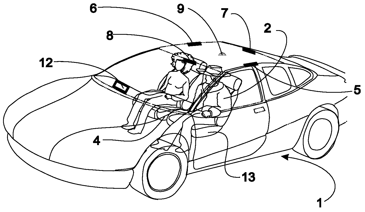
The blind spot problem for trucks is particularly difficult.
However, the truck driver is also unable to see objects that are in another blind spot extending from forward of the front of the vehicle back typically 25 feet.
Trucks also have blind spots behind the trailer that are problematic during
backup maneuvers.
The solutions presented in this patent are, however, unnecessarily complicated and alternative approaches are disclosed herein.
Any system that displays a picture of the object on the screen that is inside the vehicle is also going to confuse the driver since he or she will not be able to relate that picture to an object such as another vehicle in the blind spot on the side of the host vehicle.
Additionally, the state of the art of such displays does not provide equally
observable displays at night and in bright
sunlight.
Thus, displays on a CRT or LCD are not natural and it is difficult for a driver to adjust to these views.
The lighting of the views is too faint when
sunlight is present and too bright when the vehicle is operating at night or the brightest object is not the object of interest and can be difficult to see in the presence of brighter objects.
Therefore, none of the prior art television-like displays can replace the actual visual view of the occupant.
As a result, the display is difficult to see and interpret.
No mention is made of the use of icons and this patent is a good example of the complexity of that approach and of the
confusion that results especially when pixels which are not
observable due to blockage are displayed as black.
The cost of the CCD and
CMOS arrays, for example, have been expensive until recently, rendering their use for around vehicle area monitoring systems impractical.
Similarly, the implementation of the techniques of the above referenced patents frequently requires expensive microprocessors while the implementation with neural networks and similar trainable pattern recognition technologies permits the use of low cost microprocessors typically costing less than $10 in large quantities.
One point that is made with regard to anticipatory sensors is “The
crash pulse is still necessary because, e.g., a radar sensor cannot distinguish an empty box or concrete pillar.” Although in principle if a concrete pillar looks like an empty box, this might be true, however the frequency of this happening is vanishingly small and in those and similar cases, the system would be biased not to set off the airbags for cases where an appropriate
pattern recognition system is not sure of the identity of the object.
Side impacts were the second cause of automobile related deaths with about 8,000 fatalities each year.
The
side impact problem is considerably more difficult to solve in this way than the frontal impact problem due to the lack of space between the occupant and the side door and to the significant intrusion of the side door into the passenger compartment which typically accompanies a
side impact.
In addition, the
human body is more vulnerable to side impacts than frontal impacts and there is usually significant intrusion into the passenger compartment.
Sensors used for
side impact airbags, however, usually begin sensing the
crash only at the beginning of the impact at which time there is insufficient time remaining to move the occupant before he is impacted by the intruding door.
Even if the
airbag were inflated instantaneously, it is still not possible to move the occupant to create the desired space without causing serious injury to the occupant.
The problem is that the sensor that starts sensing the
crash when the impact has begun is already too late, i.e., once the sensor detects the crash, it is usually too late to properly inflate the
airbag.
Prior to 1994, this was not practical due to the inability to predict the severity of the accident prior to the impact.
Further, it was not possible to differentiate between these different accidents with a high
degree of certainty.
Once a sufficiently large
airbag is deployed in a side impact and the driver displaced away from the door and the
steering wheel, he will no longer be able to control the vehicle that could in itself cause a serious accident.
Anticipatory sensors have previously not been used because of their inability to predict the severity of the accident.
Karr et al. is limited to frontal crashes and rear crashes and does not appear to even remotely relate to side impacts.
Clark and Young demonstrated the concept of pre-inflating the airbag for frontal impacts but did not provide a method of determining when to inflate the airbag.
Although numerous patents have now appeared that discuss using an external airbag for the protection of pedestrians, little if any prior art exists on using anticipatory sensing for the detection of a
pedestrian and for the pre-inflating of the
pedestrian protection exterior airbag.
Twelve frames would border on being too slow.
It is difficult to believe that such a system would be used for
pedestrian detection for automobiles where hood raising or external airbags would be deployed with such a high false alarm rate.
For such automotive applications, the false alarm rate would have to be effectively zero due to the large number of non-pedestrian scenes that a vehicle encounters on every trip.
Note that the performance is not high even with a small
database and that depth segmentation will not work if pedestrians are not close to the camera.
In any event, the recommend method is too complicated and too slow for practical use.
It is a pattern-matching related approach, which has similar problems to those that have to be solved for
Radial Basis Function (RBF) and
Support Vector Machine (SVM) networks to reduce number of memorized support vectors.
It is based on leg motion and therefore is not viable for pedestrians walking head-on into or away from an oncoming vehicle.
Since the distance to a pedestrian is not recorded, it is difficult to make any judgment as to the accuracy of the system.
This is clearly too slow and requires too much
processing power so as to render this system impractical.
It makes use of
template matching which is a slow computationally intensive pattern recognition method.
Since the effective use of neural networks, as taught in the current assignee's patents, is somewhat complicated.
The fact that others might consider their use for
pedestrian detection is not an enabling statement.
While reading
Fang, Y., K. Yamada, Y. Ninomiya, B. K. P. Horn, & I. Masaki “A Shape-Independent Method for
Pedestrian Detection with Far-
Infrared Images,”IEEE Transactions On Vehicular Technology, Vol. 53, No. 5, September 2004, it becomes obvious that the authors of this paper, as well as all of the previous papers discussed above, do not really understand neural networks.
Their application of neural networks is very primitive and doomed to failure.
Also, this system is based on
thermal infrared technology and it is very difficult to get the distance to an
object based on thermal IR unless
stereo cameras are used to which also is relatively inaccurate for longer separations.
The accuracy of the system probably is poor since the distance to the pedestrian is not provided.
At six frames per second, this system is also too slow.
The accuracy is probably poor however since the accuracy is critically based on the distance from the vehicle and since this is not stated it is difficult on any of these papers to judge what the accuracy is when the pedestrian is no more than ten meters away.
The method of dividing the pedestrian to separate segments is unnecessary if one understands the basis of neural networks and it is probably a poor choice in any event.
Although it is difficult to ascertain, it looks like that for a distance of up to fifteen meters there is a ninety six percent accuracy with some false positives; however, it takes 4.6 frames to reach this accuracy which is approximately one half second which would be too slow.
In the opinion of the inventor herein, the actual capability of generalization is not as good as it sounds in this paper, and the flat-road assumption can cause problems in the real world.
The “attention mechanism” isn't described in the paper so it is difficult to evaluate it.
These are strong limitations of the
algorithm because it becomes suitable for pedestrians only.
The presented approach is also limited.
Nevertheless, the inventions herein can contribute to
safe driving in these conditions, if such driving is attempted, since an indication will be obtained by the system based on the elliptical reflections from the
laser diode indicating that the
visibility is unacceptable.

