Target interception

a target and interception technology, applied in the direction of firing/trigger mechanisms, ammunition in cartridges, launching weapons, etc., can solve the problems of difficult tracking of incoming missiles to within hit-to-kill margin of error, and the effectiveness of vehicle cross-sectional area is increased, and the effect of increasing the effective cross-sectional area

Inactive Publication Date: 2009-12-15
DEFENDTEX
View PDF52 Cites 10 Cited by
  • Summary
  • Abstract
  • Description
  • Claims
  • Application Information

AI Technical Summary

Benefits of technology

[0026]b) A number of second connectors, each second connector coupling the second connections of selected projectiles in different sets of barrels to the controller, thereby allowing the controller to apply activation signals to selected ones of the sets of first connectors and the second connectors to thereby deploy selected projectiles.
[0038]The controller can be adapted to fire the charges at predetermined time intervals to thereby control the rate of deployment of the projectiles.
[0093]a) Symmetric around the body axis to thereby equalise the reactive forces on the body; and,
[0097]The projectile deployment pattern can be selected to thereby increase the effective cross sectional area of the vehicle.

Problems solved by technology

There are a number of fundamental difficulties involved in the interception of an incoming enemy ballistic missile with a conventional interception missile or other similar kill vehicle.
In particular, engineering a hit-to-kill interception missile that can achieve intercept with any consistency is problematic, principally because of the high converging speed of the target ballistic missile and the interception missile.
Thus the speed of both the incoming missile and the interception missile make tracking the incoming missile to within a hit-to-kill margin of error, extremely difficult.
Present missile tracking technologies are quite sophisticated, however the problem remains that often quite significant changes in the trajectory of the interception missile are required but are difficult to execute.
This problem is exacerbated by the fact that typical conventional interception missiles have a relatively small cross-sectional diameter which must intercept either the front or side of the incoming enemy missile, which also has a very small cross-sectional area.
Thus, this provides a small collision cross section, meaning it is difficult to achieve the required degree of control to enable the interception missile to be in exactly the right place at the right time to achieve a direct hit and thereby eliminate the target missile.
In this case, the fragmentation causes shrapnel to be spread away from the interception missile, thereby increasing the chance of a hit on the enemy missile.
However, the majority of current fragmentation techniques utilise the detonation of an explosive charge, to project shrapnel away from the missile and do not provide a homogenous fragmentation pattern, but rather result in random and extremely haphazard shrapnel dispersion.
This means that the fragmentation radius of a detonation cannot be relied upon to increase the allowable margin of error in interception time and position of the interception missile or kill vehicle.
An additional problem with missile interception is that divert propulsion technologies are limited in their effect due to the size and weight of the interception missile, as well as its speed.
The capability of current divert propulsion systems is severely limited by the very small mass ejected in order to affect changes in trajectory.
There is not believed to be any technology currently available to satisfactorily address this threat.
Accordingly, it will be appreciated that the ability of missiles to intercept targets including other target missiles is currently limited.

Method used


Image

  • Target interception
  • Target interception
  • Target interception

Examples


Embodiment Construction

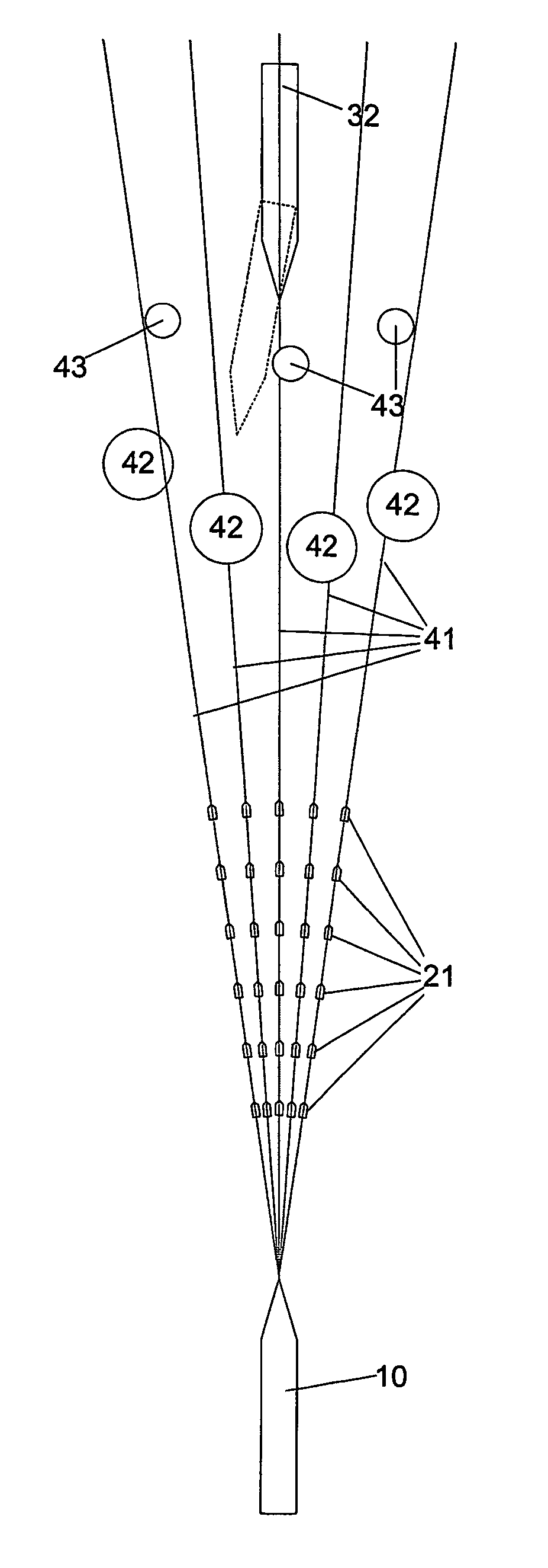
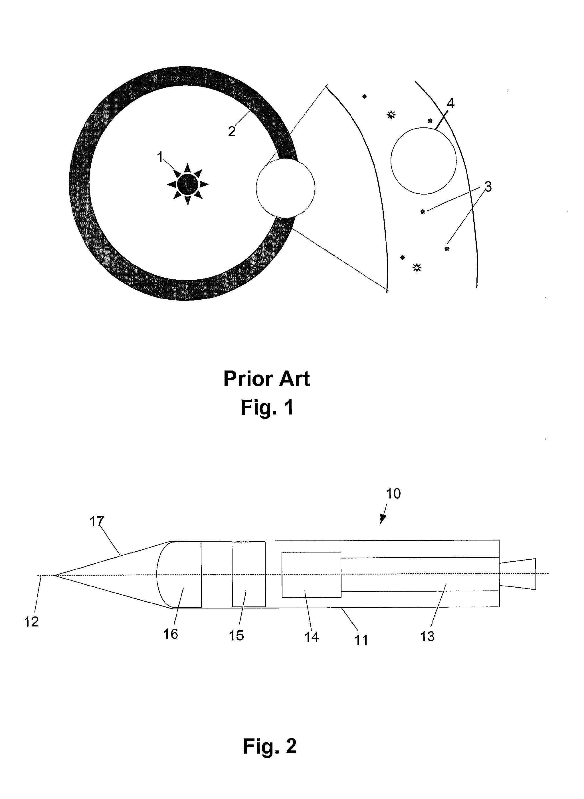
[0152]An example of a kill vehicle suitable for intercepting targets, such as other missiles, will now be described with reference to FIG. 2.

[0153]Kill vehicles may come in any one of a number of forms, depending on the circumstances in which the kill vehicle is to be used. Thus, for example, the kill vehicle could be adapted to be used above the earth's atmosphere in orbital applications, for example to intercept targets such as ICBMs. In this case, the kill vehicle will generally be launched into orbit by appropriate rocket systems, such as a missile, or the like, and then deployed into orbit ready for subsequent use. Alternatively, the kill vehicle may be integrated into a missile, allowing the missile to deploy projectiles, as will be described below.

[0154]An example of a typical kill vehicle construction is shown in FIG. 2. In this example, the kill vehicle 10 includes a body 11 having a generally cylindrical shape defining a body axis 12. The body generally includes a propulsi...


PUM


Abstract

A projectile deployment system for use in intercepting a target (32) wherein the system includes a body (10) defining a body axis, and a number of barrels (30) circumferentially spaced around the body axis. Each of the barrels (30) contains a number of projectiles (31) axially stacked therein, with a corresponding number of charges being provided such that each charge is associated with a respective projectile (31) along barrel (30). Each of the charges is individually activated to deploy a respective projectile (31) in response to a signal from a controller.

Description

CROSS-REFERENCES TO RELATED APPLICATIONS[0001]The present patent application is a national phase application of International Application No. PCT / AU03 / 001034 filed Aug. 15, 2003, which claims priority from Australian Application No. 2002950846 filed Aug. 16, 2002.BACKGROUND OF THE INVENTION[0002]The present invention relates to a projectile deployment device for use in a target intercept device, and method for intercepting a target and in particular to projectiles deployment devices for use in kill vehicles and missile defence systems for intercepting missiles such as ballistic missiles.DESCRIPTION OF THE PRIOR ART[0003]The reference to any prior art in this specification is not, and should not be taken as, an acknowledgment or any form of suggestion that the prior art forms part of the common general knowledge.[0004]There are a number of fundamental difficulties involved in the interception of an incoming enemy ballistic missile with a conventional interception missile or other sim...

Claims


Application Information

Patent Timeline
Patent Type & Authority Patents(United States)
IPC IPC(8): F42B12/58F41F1/00F41A19/65F42B5/03
CPCF41A19/65F42B12/58F42B5/035
Inventor O'DWYER, SEAN PATRICK
Owner DEFENDTEX
Why Eureka
Try Eureka