Premix burner for operating a combustion chamber

a technology of pre-mix burner and combustion chamber, which is applied in the direction of combustion type, combustion of lump and pulverulent fuel, lighting and heating apparatus, etc., can solve the problems of simple scaling, ineffective, and affecting the entire combustion and the emission of heat, so as to remove the disadvantages and risks associated with the effect of reducing the number o

Active Publication Date: 2009-12-15
ANSALDO ENERGIA SWITZERLAND AG
View PDF16 Cites 8 Cited by
  • Summary
  • Abstract
  • Description
  • Claims
  • Application Information

AI Technical Summary

Benefits of technology

[0015]In principle, the burner shells radially defining the swirl space, which are described solely by a partial cone shape, are aerodynamically designed in such a way that feed air flow flowing through air inlet slots into the swirl space is directed largely free of losses, i.e., without any marginal vortex formation, between two burner shells defining the air inlet slot. Due to the burner shell geometry which is designed in a conventional manner as thin deflecting baffles redirecting the feed air flow, a feed air flow flowing through the air inlet slots, along a surface, facing the feed air flow, of the burner shell, is first of all accelerated continuously when entering the air inlet slot and is successively deflected until the air flow leaves the burner shell toward the swirl space. The burner shell geometry therefore has differently shaped surface regions which laterally define the air inlet slot and by which the air flow flowing radially into the air inlet slot is deflected largely without resistance, and without the formation of a marginal flow vortex close to the surface, into the swirl space for forming a swirl flow spreading axially relative to the burner. In this way, any backflow zones forming in hitherto known premix burners having multi-shell arrangements can be avoided, in which backflow zones gas accumulations are also able to form, which by spontaneous deflagration may lead to damage to the premix burner structure and in particular to the burner shells.

Problems solved by technology

In this case, the spatial position of the premix flame is determined by the aerodynamic behavior of the swirl flow, the swirl coefficient of which increases with increasing spread along the burner axis and thus becomes unstable and ultimately breaks down into an annular swirl flow due to a discontinuous transition between burner and combustion chamber, with a backflow zone being formed, in whose front region in the direction of flow a premix flame forms.
For example, if it is not possible to spatially stabilize that part of the forming backflow zone which is right at the front in the direction of flow, thermoacoustic vibrations or pulsations occur to an intensified degree within the combustion system and considerably impair the entire combustion and the emission of heat.
Theoretical considerations and tests have shown that simple scaling, for example, of a double cone burner known from EP 0 321 809 B1, is not successful, especially since, as already mentioned above, the burner length would increase disproportionately.
There is also the fact that the width of the air inlet slots which run tangentially in the burner axis and through which the combustion feed air for generating the desired swirl flow flows into the swirl generator would likewise increase proportionally, so that good intermixing of fuel and combustion air can no longer be ensured to a sufficient quality.
However, it has been found that no satisfactory intermixing results are obtained with such multi-shell arrangements, especially since aerodynamic problems occur which in all probability can be attributed to backflow zones forming locally in the region of the individual burner shells.
This leads firstly to efficiency losses, but also entails risks if combustible fuel can collect in such backflow zones and ultimately ignite.

Method used


Image

  • Premix burner for operating a combustion chamber
  • Premix burner for operating a combustion chamber
  • Premix burner for operating a combustion chamber

Examples


Embodiment Construction

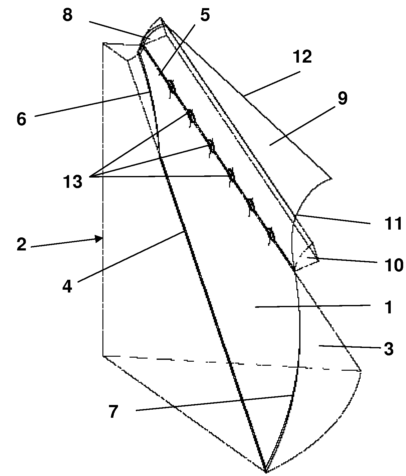
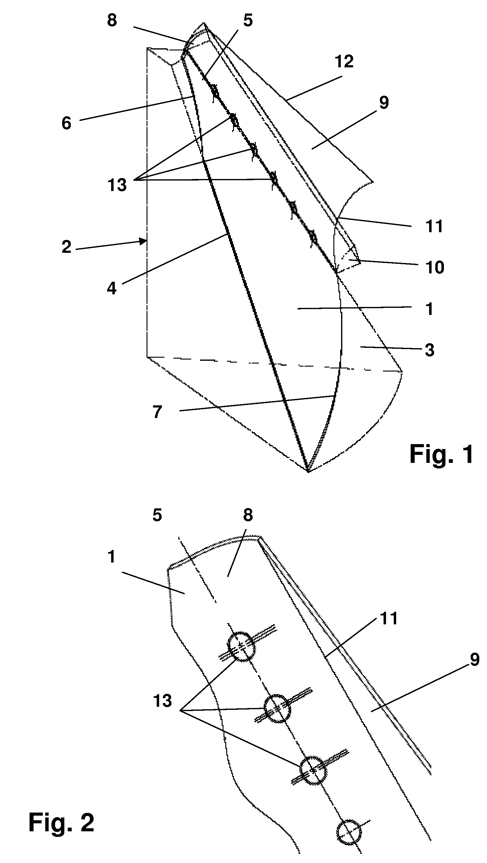
[0024]Schematically shown in FIG. 1 is an exemplary burner shell designed according to principals of the present invention, having a first burner shell section 1 which can be described by the lateral surface shape of a partial cone. Shown as an auxiliary construction in order to make it easier to illustrate the geometrical design of the first burner shell section 1 is a partial segment 2 of a cone body, along the conical lateral surface 3 of which the first burner shell section 1 bears in a conforming manner. It may be noted at this point that the first burner shell section 1 corresponds to the shape of any burner shells used hitherto, the side edge 4 which is longer in the exemplary embodiment according to FIG. 1 corresponding to the trailing edge of the burner shell, and the front edge, indicated by the continuous line 5, of the burner shell section 1 corresponding to the leading edge of a hitherto conventional burner shell. As can be seen below with reference to the three-dimensi...


PUM


Abstract

A premix burner for producing an ignitable fuel / air mixture has a swirl generator with at least two burner shells (B) which complement one another to form a throughflow body, which in each case have a first burner shell section (1) with a partial cone shape and together enclose an axially conically widening swirl space and which mutually define, in the axial cone longitudinal direction, tangential air inlet slots (LS), through which the combustion feed air (L) passes into the swirl space, in which an axially spreading swirl flow forms, and includes fuel feeds which are arranged at least in sections along the tangentially running air inlet slots (LS). A second burner shell section (8) curved in opposition to the first burner shell section (1), in each case designed in a partial cone shape, is added flush to the first burner shell section (1), a third burner shell section (9) adjoins the second burner shell section (8) flush, the third burner shell section (9) having a curvature tangentially adapted to the second burner shell section (8), and the third burner shell section (9) defines, on the one side in each case, one of the tangential air inlet slots (LS) and provides a leading edge (12) serving for the combustion feed air (L).

Description

[0001]This application is a Continuation of, and claims priority under 35 U.S.C. § 120 to, International application number PCT / EP2006 / 060437, filed 3 Mar. 2006, and claims priority therethrough under 35 U.S.C. § 119 to Swiss application number 00409 / 05, filed 9 Mar. 2005, the entireties of which are incorporated by reference herein.BACKGROUND[0002]1. Field of Endeavor[0003]The invention relates to a premix burner for producing an ignitable fuel / air mixture, including a swirl generator which provides at least two burner shells which complement one another to form a throughflow body, which in each case have a first burner shell section designed in a partial cone shape and together enclose an axially conically widening swirl space and which mutually define in the axial cone longitudinal extension tangential air inlet slots, through which the combustion feed air passes into the swirl space, in which an axially spreading swirl flow forms, and comprising a device for spraying fuel arrang...

Claims


Application Information

Patent Timeline
Patent Type & Authority Patents(United States)
IPC IPC(8): F23D14/46
CPCF23C7/002F23D14/02F23C2900/07002
Inventor STEINBACH, CHRISTIANVON PLANTA, MARTIN ANDREARUCK, THOMASGENG, WEIQUN
Owner ANSALDO ENERGIA SWITZERLAND AG
Why Eureka
Try Eureka