
Dense, shaped articles constructed of a refractory material and methods of preparing such articles

a technology of refractory material and shaped articles, which is applied in the direction of thin material processing, crystal growth process, domestic applications, etc., can solve the problems of limited choice of hot zone material of reactor, selection of reaction crucibles, plasma spray process, etc., and achieve high utilization yield

Active Publication Date: 2009-12-15
NORTH CAROLINA STATE UNIV +6
View PDF13 Cites 13 Cited by
  • Summary
  • Abstract
  • Description
  • Claims
  • Application Information

AI Technical Summary

Benefits of technology

[0009]The present invention provides a two-stage process for fabrication of dense, near-net shapes made of refractory materials. Advantageous features of certain embodiments of the inventive process include: (1) allowing precise machining of shapes before they are densified and rendered extremely hard; (2) offering high utilization yield of expensive starting materials (close to 100%, depending on desired shape); (3) imposing practically no constraints on the shape or thickness of the final product; and (4) offering uniform materials properties across the entire shape. All these advantages are considered major shortcomings of the competing plasma-spray processes.

Problems solved by technology

The elevated temperature requirements, combined with the chemically aggressive nature of the Al vapor, severely limit the choice of reactor hot zone materials, and most notably, the selection of reaction crucibles.
However, plasma-spray processes have several drawbacks.
For example, plasma-spray processes do not allow precise machining of shapes before they are densified and rendered too hard for conventional metal machining tools.
Further, plasma-spray processes are characterized by relatively low yields, which is problematic due to the high cost of most refractory materials, and are limited in the thicknesses and shapes that can be formed.

Method used


Image

  • Dense, shaped articles constructed of a refractory material and methods of preparing such articles
  • Dense, shaped articles constructed of a refractory material and methods of preparing such articles
  • Dense, shaped articles constructed of a refractory material and methods of preparing such articles

Examples


Embodiment Construction

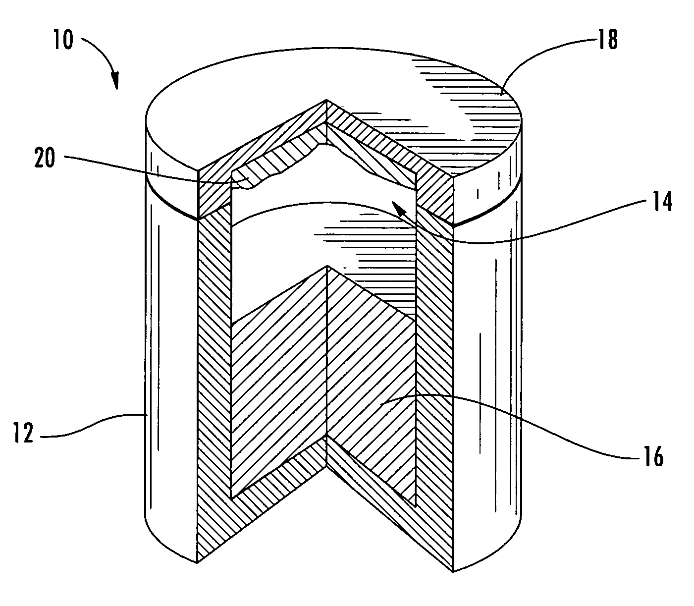
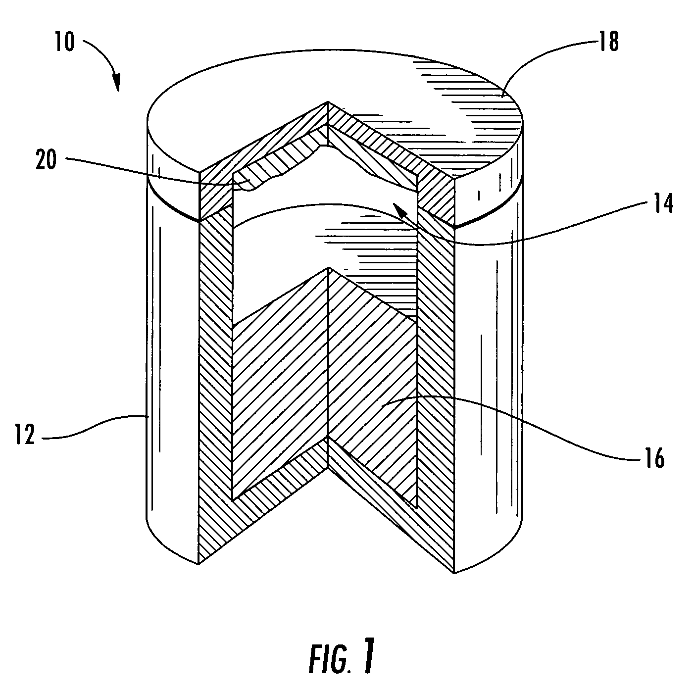
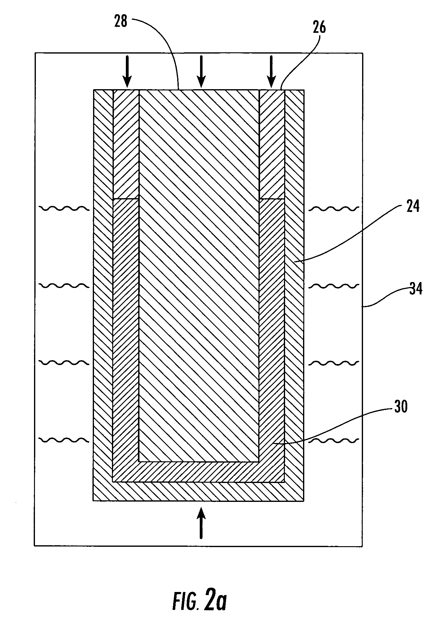
[0020]The present inventions now will be described more fully hereinafter with reference to the accompanying drawing, in which one, but not all embodiments of the inventions are shown. Indeed, these inventions may be embodied in many different forms and should not be construed as limited to the embodiments set forth herein; rather, these embodiments are provided so that this disclosure will satisfy applicable legal requirements. Like numbers refer to like elements throughout. As used in the specification, and in the appended claims, the singular forms “a”, “an”, “the”, include plural referents unless the context clearly dictates otherwise.

[0021]The present invention provides a method of forming a dense shaped article constructed of a refractory material. The refractory material used to construct the article preferably has a melting point of at least about 2900° C., more preferably at least about 3200° C., and most preferably at least about 3600° C. In some embodiments, the melting p...


PUM

PropertyMeasurementUnit
melting pointaaaaaaaaaa
porosityaaaaaaaaaa
porosityaaaaaaaaaa

Abstract

The invention provides a method of forming a dense, shaped article, such as a crucible, formed of a refractory material, the method comprising the steps of placing a refractory material having a melting point of at least about 2900° C. in a mold configured to form the powder into an approximation of the desired shape. The mold containing the powder is treated at a temperature and pressure sufficient to form a shape-sustaining molded powder that conforms to the shape of the mold, wherein the treating step involves sintering or isostatic pressing. The shape-sustaining molded powder can be machined into the final desired shap and then sintered at a temperature and for a time sufficient to produce a dense, shaped article having a density of greater than about 90% and very low open porosity. Preferred refractory materials include tantalum carbide and niobium carbide.

Description

CROSS REFERENCE TO RELATED APPLICATIONS[0001]This application claims the benefit of U.S. Provisional Application No. 60 / 668,744, filed Apr. 6, 2005, which is incorporated herein by reference in its entirety and for all purposes.FEDERALLY SPONSORED RESEARCH OR DEVELOPMENT[0002]The research underlying this invention was supported in part with funds from Office of Naval Research (ONR) grant no. N00014-01-1-0716. The United States Government has certain rights in this invention.FIELD OF THE INVENTION[0003]The present invention relates to dense, shaped articles comprising a refractory material, such as crucibles suitable for use in bulk crystal growth by physical vapor transport. The invention also relates to methods of fabricating dense shaped articles using a sintering step.BACKGROUND OF THE INVENTION[0004]The growth of aluminum nitride (AlN) bulk crystals by sublimation of an AlN source requires elevated temperatures, typically in a range of 1800° C. to 2300° C., with the upper end of...

Claims


Application Information

Patent Timeline
Patent Type & Authority Patents(United States)
IPC IPC(8): B22F1/02
CPCC22C1/045C30B23/00C30B29/36C30B23/066B22F5/007C04B35/56C04B35/5607C04B35/64C04B35/645C04B35/6455C04B2235/6567Y10T428/13C04B2235/77C04B2235/94C04B2235/661C04B2235/6565C04B2235/6562C04B2235/612C04B2235/608C04B2235/604C04B2235/602B22F2998/10B22F2999/00B22F3/02B22F3/04B22F3/1007B22F3/14B22F2201/20
Inventor SCHLESSER, RAOULDALMAU, RAFAEL F.NOVESKI, VLADIMIRSITAR, ZLATKO
Owner NORTH CAROLINA STATE UNIV
Learn More