Spectroscopic ellipsometer and polarimeter systems

a technology of ellipsometer and polarimeter, which is applied in the direction of interferometric spectrometry, optical radiation measurement, instruments, etc., can solve the problems of increased heat production and accompanying production of ozone levels to which personnel cannot be safely exposed, unacceptably distributed produced ozone into surrounding atmosphere, and rotating compensator ellipsometer systems do not demonstrate “dead spots”

Inactive Publication Date: 2009-12-15
J A WOOLLAM CO
View PDF59 Cites 111 Cited by
  • Summary
  • Abstract
  • Description
  • Claims
  • Application Information

AI Technical Summary

Benefits of technology

[0204]Further, at least one of the elements can comprise a mechanism for translating and / or tilting at least one of the elements with respect to another element, for the purpose of aligning the elements of the system so as to reduce deviation between the locus of an output beam as compared to that of a beam input to said system.
[0257]A preferred means for allowing produced ultraviolet radiation to exit as a collimated beam comprises a pin hole and lens means present inside a protective tube which serves to prevent air flow by said lens means.

Problems solved by technology

A problem inherent in operation, however, is that to increase intensity output therefrom or extend the useable wavelength range lower limit to say 220 nm or even 160 nm and below, results in increased heat production and accompanying production of levels of ozone to which personnel can not be safely exposed.
The temperature of the source can be controlled by flowing a gas therearound to dissipate increased heat, but this also serves to unacceptably distribute produced ozone into surrounding atmosphere when it is produced.
It is noted that rotating compensator ellipsometer systems do not demonstrate “dead-spots” where obtaining data is difficult.
They can read PSI and DELTA of a material system over a full range of degrees with the only limitation being that if PSI becomes essentially zero (0.0), one can't then determine DELTA as there is not sufficient PSI polar vector length to form the angle between the PSI vector and an “X” axis.

Method used


Image

  • Spectroscopic ellipsometer and polarimeter systems
  • Spectroscopic ellipsometer and polarimeter systems
  • Spectroscopic ellipsometer and polarimeter systems

Examples


Embodiment Construction

Invention System

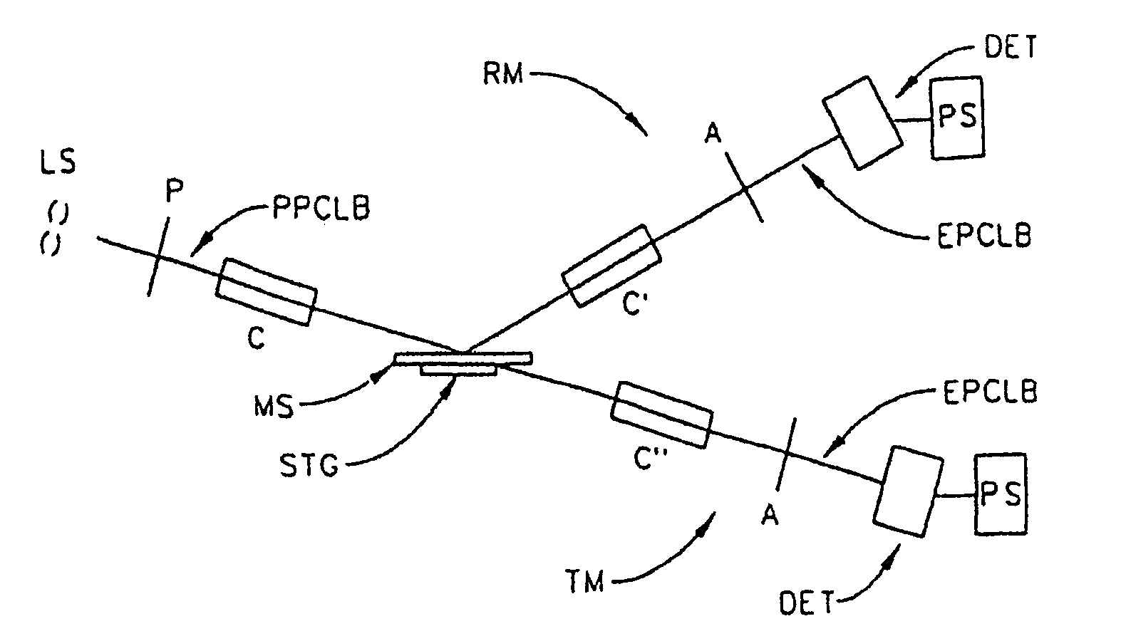
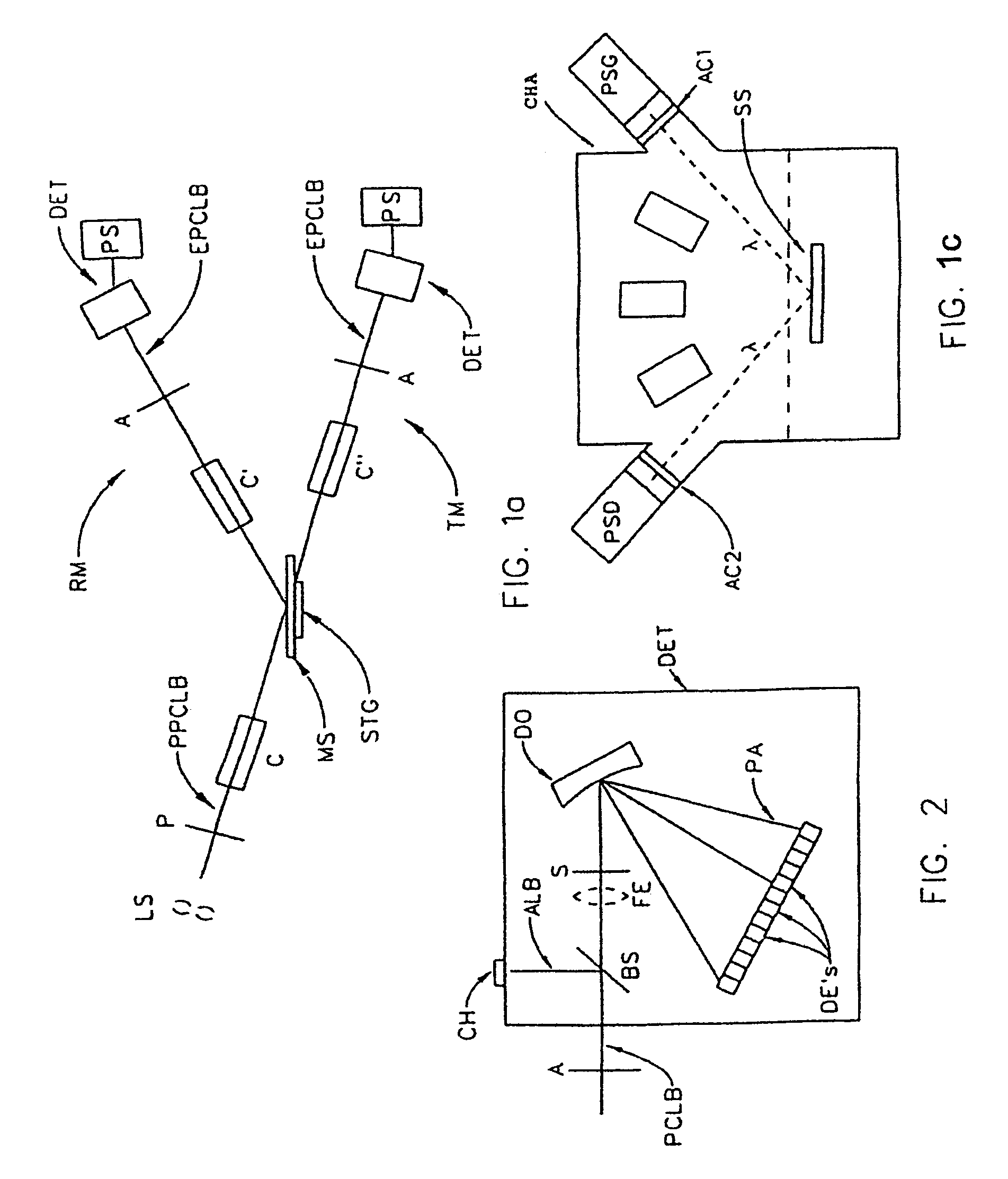
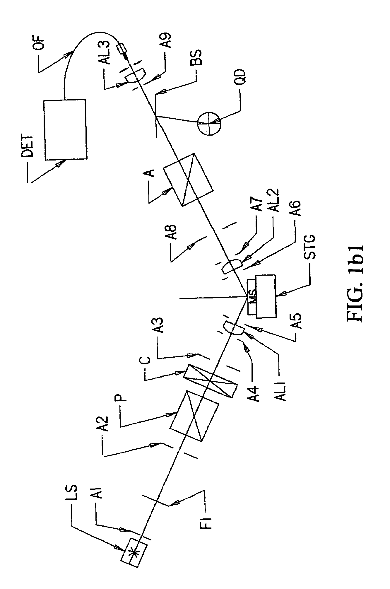
[0322]Referring now to FIG. 1a, there is demonstrated a Material System Investigation System, (ie. a Spectroscopic Ellipsometer System), with provision to investigate a Material System (MS) in either a Reflection Mode (RM) or a Transmission Mode (TM). It is to be noted that said Material System investigation System is generally comprised of a Source of a Polychromatic Beam of Electromagnetic Radiation (LS), (ie. a Broadband electromagnetic radiation source), a Polarizer Means (P), a Material System, supporting Stage (STG), an Analyzer Means (A) and a Detector Elements (DE's) containing Photo Array Detector Means System (DET). Also note, however, that FIG. 1a shows Reflection Mode System Compensator(s) Means (C) and (C′) and Transmission Mode System Compensator(s) Means (C) and (C″) as present. It is to be understood that a Compensator Means can be placed ahead of, and / or after a Material System (MS) supporting Stage (STG) in either a Reflection Mode or Transmission M...


PUM


Abstract

A rotating compensator spectroscopic ellipsometer or polarimeter system having a source of a polychromatic beam of electromagnetic radiation, a polarizer, a stage for supporting a material system, an analyzer, a dispersive optics and a detector system which comprises a multiplicity of detector elements, the system being functionally present in an environmental control chamber and therefore suitable for application in wide spectral range, (for example, 130-1700 nm). Preferred compensator design involves a substantially achromatic multiple element compensator systems wherein multiple total internal reflections enter retardance into an entered beam of electromagnetic radiation, and the elements thereof are oriented to minimize changes in the net retardance vs. the input beam angle resulting from changes in the position and / or rotation of the system of elements.

Description

[0001]This Application is a CIP of application Ser. No. 11 / 497,921 Filed Aug. 3, 2006; now U.S. Pat. No. 7,489,400 and therevia of application Ser. No. 10 / 613,051 Filed Jul. 7, 2003; now U.S. Pat. No. 7,009,006 and therevia Claims benefit of 60 / 229,755 filed Sep. 5, 2000. This Application is also a Continuation-in-Part of Co-Pending application Ser. No. 09 / 945,962 Filed Sep. 4, 2001, now U.S. Pat. No. 7,075,649 and therevia of application Ser. No. 09 / 517,125 Filed Feb. 29, 2000; (now abandoned); and of Ser. No. 09 / 246,888 filed Feb. 8, 1999, (now U.S. Pat. No. 6,084,675);and further of Ser. No. 09 / 225,118 Jan. 4, 1999 (now U.S. Pat. No. 6,084,674); Ser. No. 09 / 223,822 Jan. 4, 1999 (now U.S. Pat. No. 6,118,537); Ser. No. 09 / 232,257 Jan. 19, 1999 (now U.S. Pat. No. 6,141,102); Ser. No. 09 / 225,371 Jan. 4, 1999 (now U.S. Pat. No. 6,100,981); Ser. No. 09 / 225,076 Jan. 4, 1999 (now U.S. Pat. No. 5,963,325); which Applications depended from Ser. No. 08 / 997,311 filed Dec. 23, 1997, (now U.S....

Claims


Application Information

Patent Timeline
Patent Type & Authority Patents(United States)
IPC IPC(8): G01B9/02G01J3/45G01J4/00
CPCG01J3/02G01J3/0213G01J3/0224G01N21/211G01N21/274G01J3/10G01N2021/213
Inventor WOOLLAM, JOHN A.JOHS, BLAINE D.HERZINGER, CRAIG M.HE, PINGLIPHARDT, MARTIN M.PFEIFFER, GALEN L.
Owner J A WOOLLAM CO
Why Eureka
Try Eureka