
100% duty-cycle buck-derived and 0% duty-cycle boost-derived power factor corrected (PFC) 3-phase Ac-Dc power converters

Inactive Publication Date: 2009-12-15
HERBERT EDWARD
View PDF4 Cites 37 Cited by
  • Summary
  • Abstract
  • Description
  • Claims
  • Application Information

AI Technical Summary

Benefits of technology

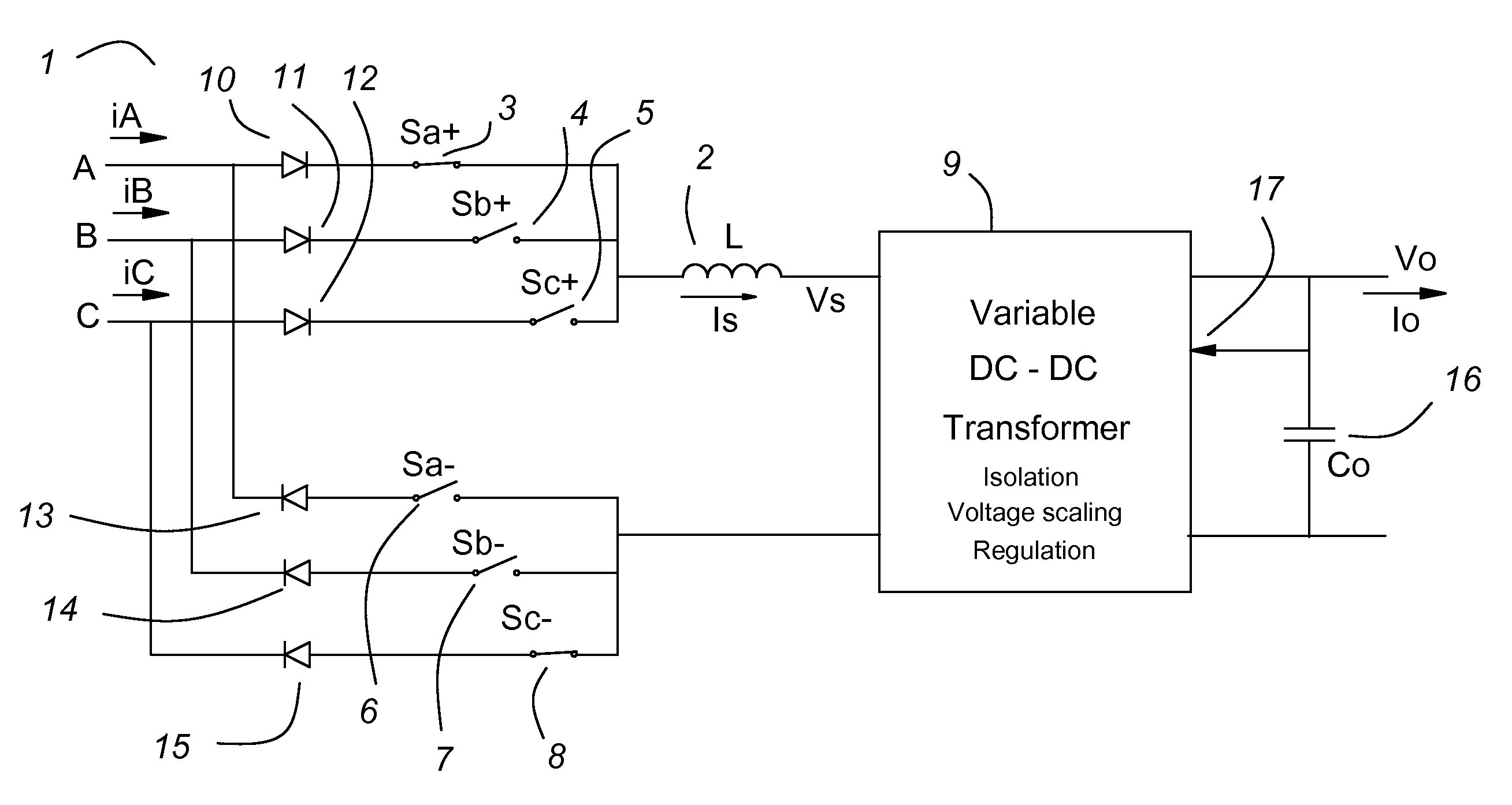
[0018]This invention teaches that a boost pfc 3-phase ac-dc power converter can be operated at 0% duty-cycle to maximize the efficiency of the pfc input.
[0019]This invention teaches that a buck pfc 3-phase ac-dc power converter can be operated at 100% duty-cycle to maximize the efficiency of the pfc input.

Problems solved by technology

Prior art pfc circuits are sluggish, difficult to control and inefficient.

Method used


Image

  • 100% duty-cycle buck-derived and 0% duty-cycle boost-derived power factor corrected (PFC) 3-phase Ac-Dc power converters
  • 100% duty-cycle buck-derived and 0% duty-cycle boost-derived power factor corrected (PFC) 3-phase Ac-Dc power converters
  • 100% duty-cycle buck-derived and 0% duty-cycle boost-derived power factor corrected (PFC) 3-phase Ac-Dc power converters

Examples


Embodiment Construction

[0058]In the drawings, the same reference designator used in different drawings is the same item. In FIGS. 32 and 33, some small graphs are labeled with the same reference designator as the switches for which they are showing the duty-cycle.

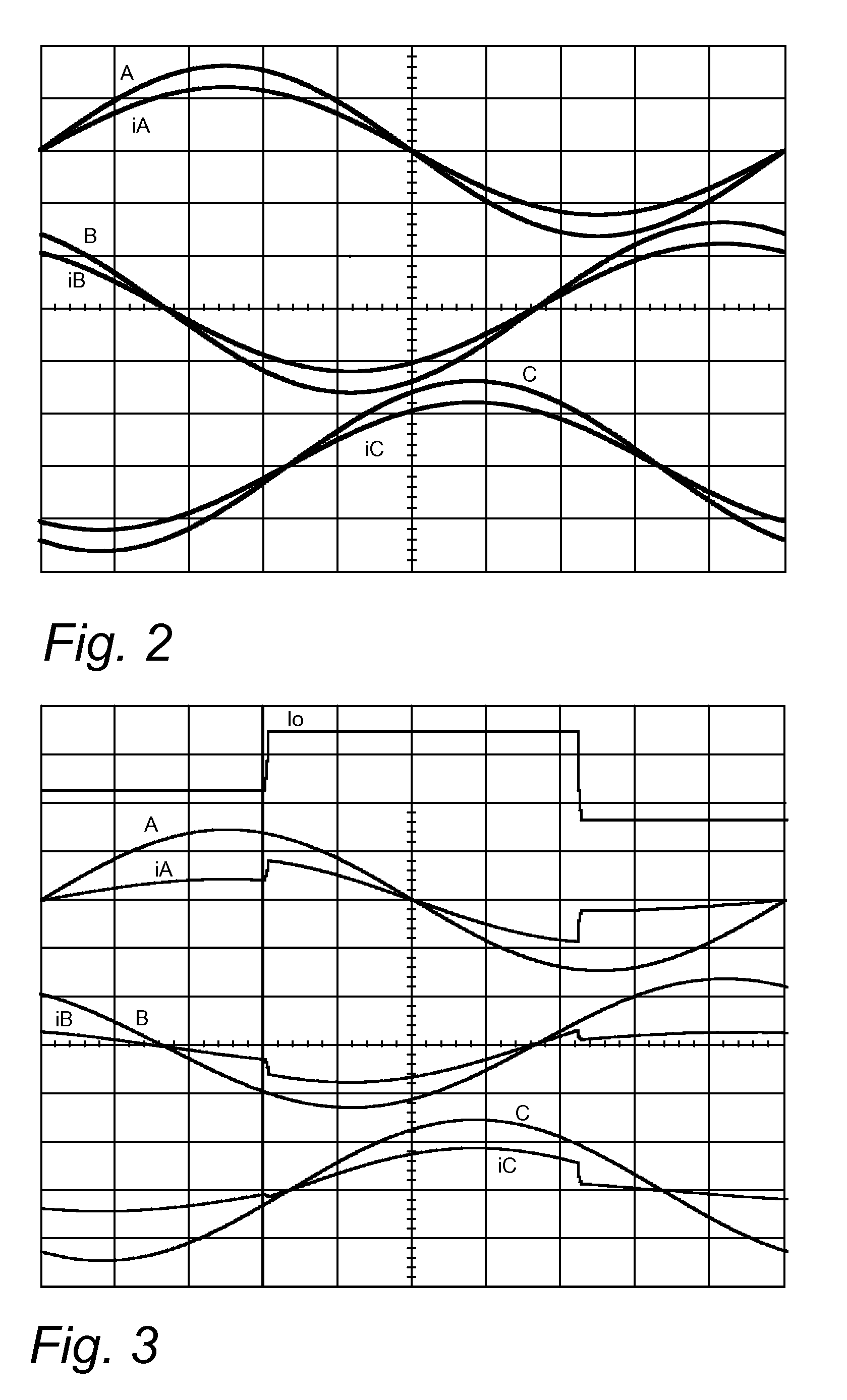
[0059]Natural modulation is control by algorithm. The control algorithm uses measurement of the input voltage and feedback from the output voltage. Once the control algorithms are well understood, circuits implementing the control algorithms can be optimized for maximum efficiency. During normal operation, the duty-cycles of the power converters of this invention are determined by “natural modulation”, that is, they are forced by a fixed algorithm that has been optimized for efficient switching. The duty-cycles do not regulate the output voltage but the do force the input currents to be proportionately correct for good power factor. A feedback control circuit controls the effective turns ratio of a variable transformer to regulate the output volt...


PUM


Abstract

This invention teaches power factor corrected 3-phase ac-dc power converters in which the duty-cycles are determined by “natural modulation”, that is, they are forced by a fixed algorithm that has been optimized for efficient switching. The duty-cycles do not regulate the output voltage but they do force the input currents to be proportionately correct for good power factor. A feedback control circuit modulates the effective turns-ratio of a variable dc-dc transformer to regulate the output voltage. For a buck converter, the most efficient duty-cycle is 100%, that is, the buck switch is always on. For a boost converter, the most efficient duty-cycle is 0%, that is, the boost switch is always off. “100% duty-cycle” as defined for a buck 3-phase ac input means that there is no off-time. The switch duty-cycles are as follows: The duty-cycle for the phase with the highest voltage magnitude (the dominant phase) is 100%, and sum of the duty-cycles of the other two phases equals 100%. “0% duty-cycle” as defined for a boost 3-phase ac input means that the input is never short circuited line to line. The duty-cycle for the switch for the phase with the highest voltage magnitude (the dominant phase) is 0%, and switches of the other two phases modulate to control their respective input currents.

Description

CROSS REFERENCE TO RELATED PATENTS AND APPLICATIONS[0001]This application is a continuation in part of a provisional U.S. patent application Ser. No. 60 / 866,613 filed Nov. 21, 2006 and entitled “3-phase PFC Ac-Dc Converter having “100 Percent Duty-cycle””. This application is also a continuation in part of a provisional U.S. patent application Ser. No. 60 / 890,539 filed Feb. 19, 2007 and entitled “100% Duty-Cycle Buck-Derived and 0% Duty-Cycle Boost-Derived PFC 3-Phase Ac-Dc Power Converters.” Priority is claimed to the filing dates of these provisional U.S. patent applications and they are incorporated herein by reference.[0002]This application relates to U.S. Pat. No. 5,132,606, issued Jul. 21, 1992 and entitled “Method and Apparatus for Controlling the Input Impedance of a Power Converter” and U.S. Pat. No. 5,144,222, issued Sep. 1, 1992 and entitled “Apparatus for Controlling the Input Impedance of a Power Converter”. These patents are owned by the same entity as the present inve...

Claims


Application Information

Patent Timeline
IPC IPC(8): G05F1/70H02M7/02
CPCG05F1/70H02M1/4216Y02B70/126Y02B70/10
Inventor HERBERT, EDWARD
Owner HERBERT EDWARD
Learn More