
Two-stage x-ray concentrator

a concentrator and x-ray technology, applied in the direction of x-ray tube targets, convertors, instruments, etc., can solve the problems of incompatibility with hand-held or portable spectrometers, size, weight and power requirements of these devices,

Active Publication Date: 2009-12-15
THERMO NITON ANALYZERS
View PDF16 Cites 34 Cited by
  • Summary
  • Abstract
  • Description
  • Claims
  • Application Information

AI Technical Summary

Benefits of technology

The two-stage concentrator system enhances signal-to-noise ratios by converting polychromatic radiation into a monochromatic beam, reducing system size and power requirements, making it suitable for portable XRF systems while maintaining high measurement accuracy.

Problems solved by technology

The size, weight and power requirements of these spectrometers have hitherto been incompatible with hand held or portable XRF spectrometers that must not weigh more than a few pounds and must have a battery life of many hours.

Method used


Image

  • Two-stage x-ray concentrator
  • Two-stage x-ray concentrator
  • Two-stage x-ray concentrator

Examples


Embodiment Construction

[0031]In prior art x-ray focusing systems such as that depicted in FIG. 3 and described in the foregoing Background Section, which may be referred to herein as based on single-stage concentrators, the anode 305 of x-ray tube 100 is the object of the x-ray optical lens formed by focusing element 303.

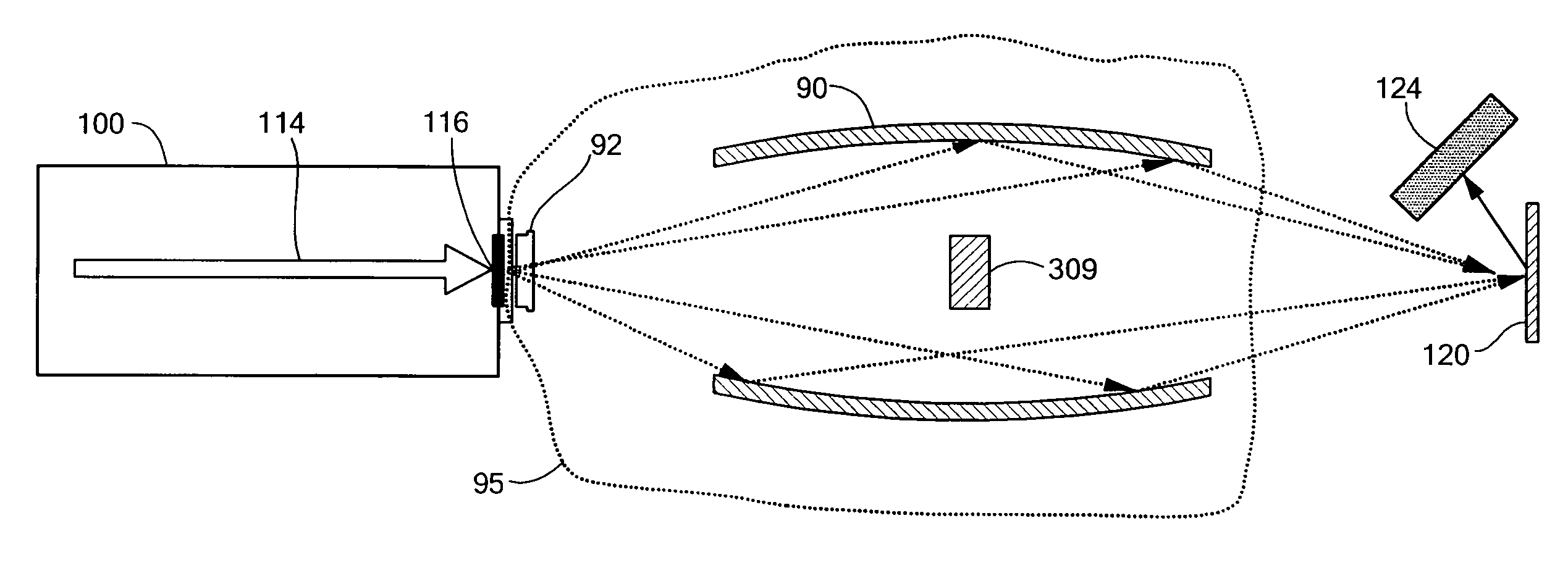
[0032]In accordance with preferred embodiments of the present invention, now described with reference to FIG. 4, a converter 400 is interposed, directly adjacent to anode 305 of x-ray tube 100 so as to convert the emitted x-rays 402, referred to herein as “first-stage” x-rays, into x-rays 404 characterized by a nearly monochromatic x-ray spectrum, referred to herein as the “second stage x-ray spectrum.” Converter 400 is now the new object of the x-ray optical lens. The method depicted may be referred to herein as a “Two-Stage Concentrator” (TSC). The optimal composition, size and thickness of the converter are selected, based upon principles to be described, in accordance with parameters ...


PUM

PropertyMeasurementUnit
distancesaaaaaaaaaa
lengthaaaaaaaaaa
energyaaaaaaaaaa

Abstract

A method for obtaining a concentrated, monochromatic x-ray beam from a standard x-ray tube or other source of polychromatic emission. X-rays from the anode of the x-ray tube fluoresce an adjoining, independent target that produces a monochromatic spectrum, a portion of which is focused by the x-ray optical system. This two-stage method gives the system considerably versatility without undue loss in signal. The two-stage concentrator makes practical the use of focusing optics in hand-held and portable instruments.

Description

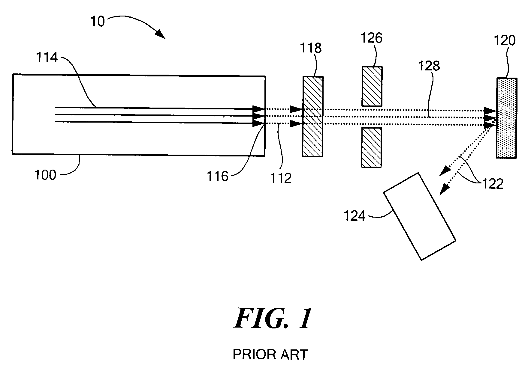
[0001]The present application claims priority from U.S. Provisional Patent Application Ser. No. 60 / 853,875, filed Oct. 24, 2006, which is incorporated herein by reference.TECHNICAL FIELD[0002]The present invention relates to methods and devices for concentrating, and concurrently spectrally filtering, x-rays from a broadband source.BACKGROUND ART[0003]Simple collimation of x-rays in conjunction with tight geometries allow hand-held analyzers based on x-ray fluorescence (XRF) to achieve high-level performance on centimeter-scale targets. FIG. 1 shows a schematic of the arrangement of components of an XRF analyzer, typified by Niton XRF analyzers manufactured by Thermo Electron Corporation, and designated, generally, by numeral 10. An x-ray tube x-ray tube 100 emits a broad spectrum of x-ray emission 112 due to the acceleration of electrons (or other charged particles) 114 toward a target, referred to herein, without limitation, as anode 116. The energy spectrum of x-ray beam 112 is t...

Claims


Application Information

Patent Timeline
Patent Type & Authority Patents(United States)
IPC IPC(8): G01N23/223G21K1/06H01J35/02
CPCG21K1/06G01N2223/316H01J2235/08G21K2201/062
Inventor GRODZINS, LEEGRODZINS, HAL
Owner THERMO NITON ANALYZERS
Learn More