

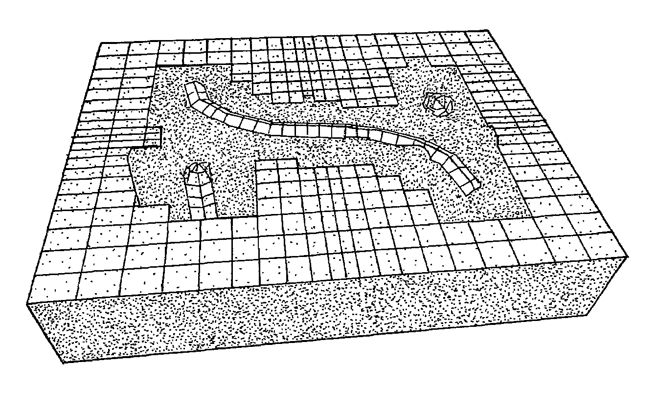
Method of generating a conforming hybrid grid in three dimensions of a heterogeneous formation crossed by one or more geometric discontinuities in order to carry out simulations
a technology of geometric discontinuities and hybrid grids, applied in the field of computer implemented methods of generating three-dimensional hybrid grids of heterogeneous formations, can solve the problems of inability to apply grid techniques used in these other fields, inability to simulate reservoirs using finite difference and finite element types, and inability to meet reservoir simulation requirements. the memory cost involved in the use of unstructured grids can become very rapidly penalized
- Summary
- Abstract
- Description
- Claims
- Application Information
AI Technical Summary
Benefits of technology
Problems solved by technology
Method used
Image

Examples
first embodiment
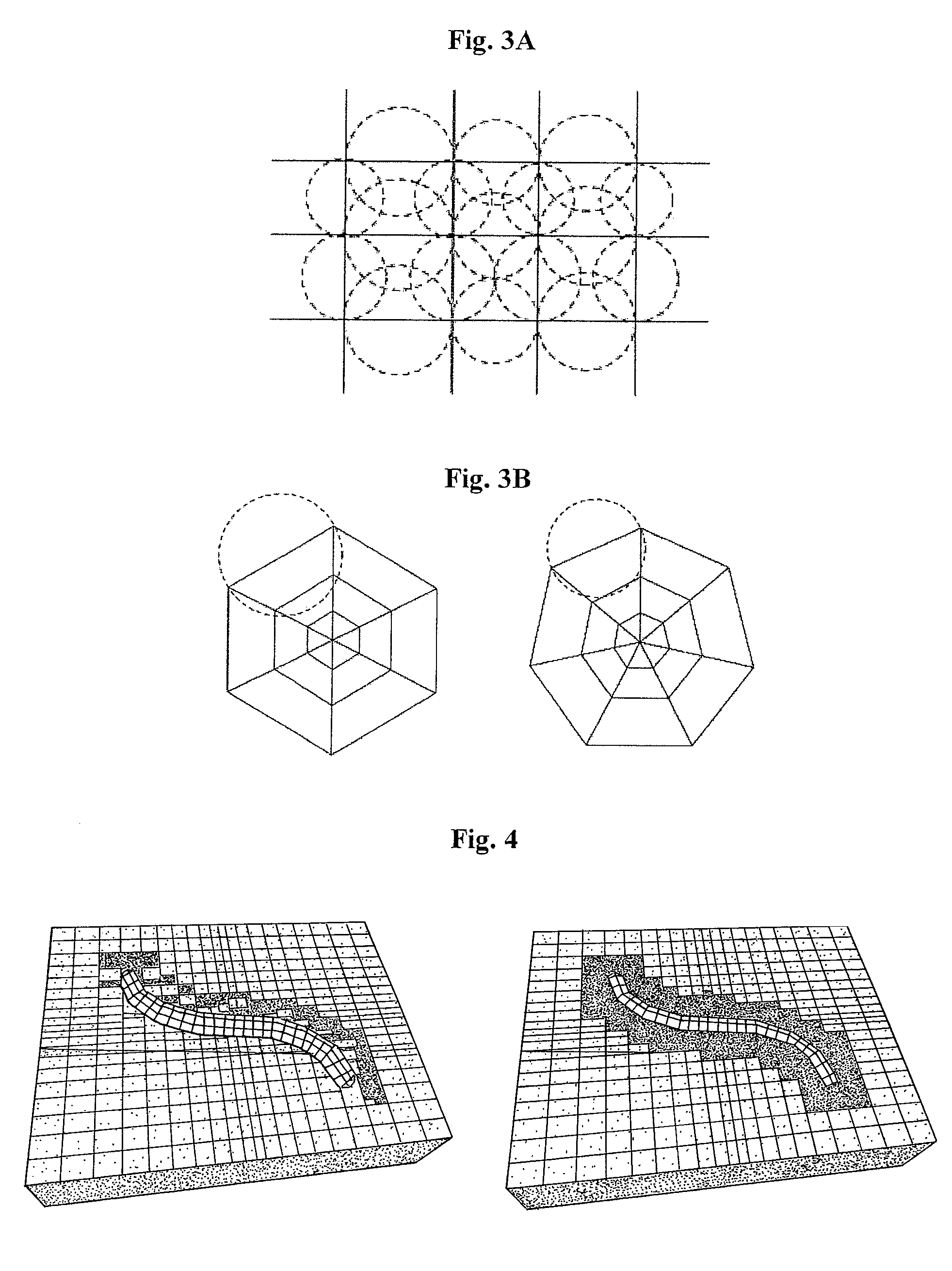
[0123]According to a first embodiment, the method is based on the construction of a Delaunay triangulation of the vertices of the cavity to define the sites of the cavity. This triangulation must be in accordance with the constraints of the cavity made up of quadrilaterals. It is therefore necessary to ensure that each side of the cavity is Delaunay admissible, that is the sides bordering the cavity belong to the Delautnay triangulation of the vertices of the cavity. The cavity is referred to as “Delaunay admissible” if the diametral sphere of each edge of the reservoir cells is empty for any vertex of the well and if the diametral sphere of each edge of the well cells is empty of any vertex of the reservoir (notion of Gabriel cavity). FIGS. 3A and 3B illustrate the Delaunay admissibility of the reservoir grid and of the well grid respectively. FIG. 3B illustrates, on the right, a Delaunay admissible grid and, on the left, a non Delaunay admissible grid. It...
second embodiment
Barycenter or Center of the Sphere Circumscribed about a Hexahedron
[0164]In the first embodiment, a Delaunay triangulation of the vertices of the cavity is used to position the sites required for construction of a conforming power diagram between the well and reservoir grids. The sites are defined on the dual edges of the sides of the cavity, so that they are located at an equal distance from the vertices of the associated quadrilateral sides. This distance is different for each site and it is a function of the space present between the boundary of the well and that of the reservoir, which is given locally by the simplexes of the triangulation.
[0165]However, the size of the cavity being known and controlled, each site of the cavity can be directly defined in such a way that the distance between a site and each vertex of the associated constraint sides is the same. The method benefits from the size of the cavity:
[0166]A)—Determination of P(x,y,z)
[0167]Selection of the Sites Associate...
PUM
 Abstract
Description
Claims
Application Information