Systems and methods for monitoring solids using mechanical resonator

a mechanical resonator and solids technology, applied in the direction of using mechanical means, process and machine control, disinfection, etc., can solve the problems of fluidized bed collapse, agglomeration, sheeting, and difficult to anticipate problems such as fluidized bed collapse, and achieve cost-effective and efficient monitoring or characterization.

Inactive Publication Date: 2009-12-22
FREESLATE
View PDF70 Cites 14 Cited by
  • Summary
  • Abstract
  • Description
  • Claims
  • Application Information

AI Technical Summary

Benefits of technology

[0147]The size of the sensing elements, especially mechanical resonator sensing elements such as flexural resonator sensing elements is not critical to the invention. In some applications, however, it should be appreciated that one advantage of the present invention is the ability to fabricate a very small sensor using the present resonators. For example, one preferred resonator has its largest dimension smaller than about 2 cm, and more preferably smaller than about 1 cm. One resonator has length and width dimensions of about 3 mm by 8 mm, and possibly as small as about 1 mm by 2.5 mm. Geometry of the resonator may be varied as desired also. For example, the aspect ratio of tines of the tuning forks, or geometrical factors of other resonators can be optimized in order to achieve better sensitivity to the properties of the gas phase, liquid phase or its particular components (e.g., a lubricant). For example, the aspect ratio of a tuning fork tine may range from about 30:1 to about 1:1. More specifically, it may range from about 15:1 to about 2:1.
[0148]It is thus seen that a preferred resonator is configured for movement of a body through a fluid. Thus, for example, as seen in FIG. 7A, the resonator may have a base and one or a plurality of tines projecting from the base. It is preferred in one aspect that any tine has at least one free tip that is capable of displacement in a fluid relative to the base. FIG. 7B illustrates a cantilever 1220 having a base 1240 and a free tip 1260. Other possible structures, seen in FIGS. 7C and 7D contemplate having a disk 1280, a plate 1300 or the like that is adapted so that one portion of it is displaceable relative to one or more variable or fixed locations 1320 (1320′). As seen in FIG. 7E, in yet another embodiment a resonator 1340 is contemplated in which a shear surface 1360 of the resonator has one or more projections 1380 of a suitable configuration, in order that the resonator may be operated in shear while still functioning consistent with the flexural or torsional resonators of the present invention, by passing the projections through a fluid.
[0149]In still other embodiments, and referring to FIGS. 7F, 7G and 7H, it is contemplated that a resonator 2000 may include an elongated member 2020 supported on its sides 2040 by a pair of arms 2060. As shown respectively in FIGS. 7F through 7H, the elongated member may be configured to oscillate side-to-side, back and forth, in twisting motions or combinations thereof.
[0150]The flexural resonator, such as the embodiment of FIG. 7B, may be constructed as a monolithic device. Yet another structure of the present invention contemplates the employment of a laminate or other multi-layer body that employs dissimilar materials in each of at least a first layer and a second layer, or a laminate comprised of layers of piezoelectric material of different orientations or configurations. According to this approach, upon subjecting one or more of the layers to a stimulus such as temperature change, an electrical signal or other stimulus, at least one of the materials will respond differently than another and the differences in responses will, in turn, result in the flexure of the resonator. In yet another embodiment, it is contemplated that plural resonators can be assembled together with an electrode at least partially sandwiched therebetween. In this manner, it may be possible to further protect electrodes from harsh conditions, while still achieving the desired flexure. One specific example might include a two or more lithium niobate or quartz tuning forks joined together with a gold electrode therebetween. Other configurations (e.g., an H-shaped resonator) and material combinations may be employed as well, as disclosed in U.S. Provisional Application Ser. Nos. 60 / 456,767 and 60 / 456,517 (both filed Mar. 21, 2003), incorporated by reference.
[0151]As can be seen, the selection of the specific resonator material, structure, or other characteristic will likely vary depending upon the specific intended application. Nonetheless, it is preferred that for each application, the resonator is such that one or a combination of the following features (and in one highly preferred embodiment, a combination of all features) is present: a coating, if placed upon the resonator in a thickness greater than about 0.1 micron, will not substantially detract from resonance performance; the resonator is operable and is operated at a frequency of less than about 1 MHz, and more preferably less than about 100 kHz; the resonator is substantially resistant to contaminants proximate to the sensor surface; the resonator operates to displace at least a portion of its body through a mass of particles in a nonfluidized bed; or the resonator responses are capable of de-convolution for measuring one or more individual properties of the particles and / or multi-phase system.
[0152]The resonator may be uncoated or coated or otherwise surface treated over some or all of its exterior surface. A preferred coating is a metal (e.g., a conductive metal similar to what may be employed for electrodes for the sensor, such as silver, gold, copper, aluminum or the like), plastic, ceramic or composite thereof, in which the coating material is substantially resistant to degradation from the fluid to which it is to be exposed or to surface build-up, over a broad temperature range. For example, one preferred embodiment, contemplates the employment of a base resonator material and a performance-tuning material. Among the preferred characteristics of the resonators of the present invention is the base material is generally thermally stable. For example, in one preferred embodiment, the material exhibits a dielectric constant that is substantially constant over a temperature range of about 0° C. to about 100° C., more preferably about −20° C. to about 150° C., and still more preferably about −40° C. to about 200° C. For example, it is contemplated that a preferred material exhibits stability to a temperature of at least about 300° C., and more preferably at least about 450° C. in order to withstand the heat of reaction in a fluidized bed polymerization reactor vessel. In another aspect, the dielectric constant of the performance-tuning material preferably is greater than that of quartz alone, such as by a factor of 5 or more, more preferably by a factor of 10 or more and still more preferably by a factor of 20 or more.

Problems solved by technology

Because fluidized bed systems are often closed, it is difficult to monitor definable parameters and changes in condition, e.g., how the bed and its components are presently behaving and reacting to process changes, the level of product in the vessel, etc.
This in turn makes it difficult to anticipate problems such as fluidized bed collapse, agglomeration, and sheeting.
Fluidized bed collapse can generally have undesirable consequences.
In a fluidized bed polymerization reactor system, fluidized bed collapse is a very costly occurrence, both in terms of production time lost, and often the need to physically remove agglomerations from the reactor system before the fluidized bed can be reinitiated.
Another issue requiring attention is how to ensure uniform fluidization of the bed.
Non-uniform fluidization of the bed can create “hot spots,” which in turn can cause the newly-formed polymer particles to become tacky due to elevated temperatures.
The tackiness can cause particle agglomeration, and more devastatingly, sheeting.
In agglomeration, the particles stick together, forming agglomerated particles that affect fluid flow and may be difficult to remove from the system.
Sheeting is particularly malicious in that a sheet falling from the reactor wall can damage system components such as sensors as well as disrupt fluid flow resulting in collapse of the fluidized bed.
Again, the lost production time is very costly.
Thermocouples are used as sensors in the fluidized bed polymerization industry and are effective at detecting the local temperature of a gas flowing near the reactor wall, however, they provide very little indication of a uniformity of the bed.
Nor do they provide any indication of a tackiness of the particles or if sheeting is occurring.

Method used


Image

  • Systems and methods for monitoring solids using mechanical resonator
  • Systems and methods for monitoring solids using mechanical resonator
  • Systems and methods for monitoring solids using mechanical resonator

Examples


Embodiment Construction

[0041]The following paragraphs describe certain features and combinations of features that can be used in connection with each of the methods, systems and apparatus of the invention, as generally described above. Also, particular features described hereinafter can be used in combination with other described features in each of the various possible combinations and permutations. As such, the invention is not limited to the specifically described embodiments.

Preferred General Methods

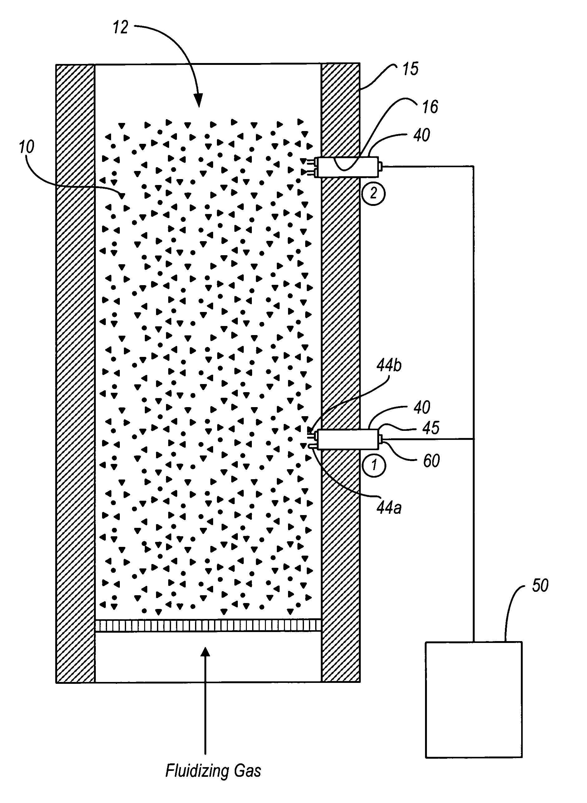
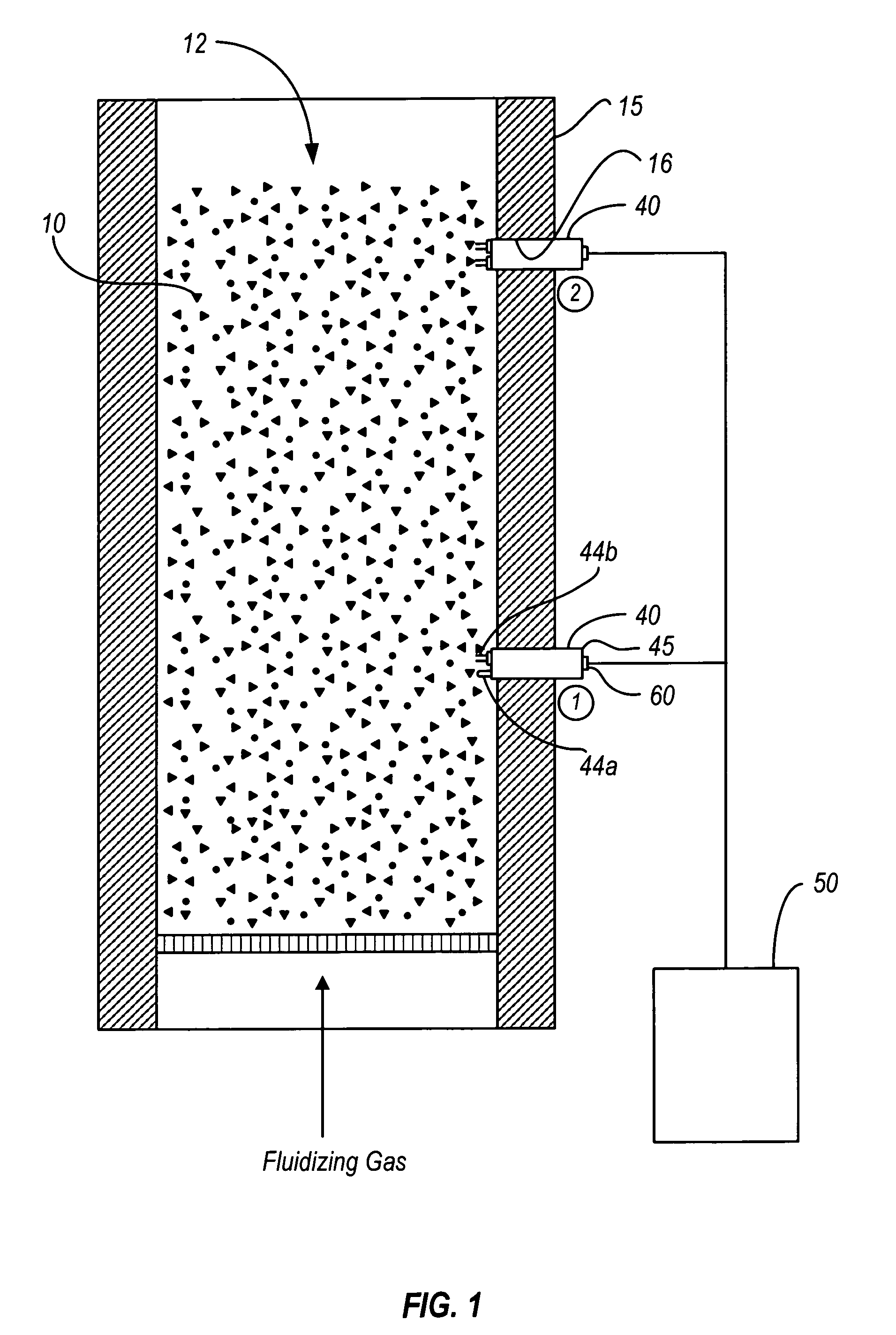
[0042]A preferred general method of the invention can be described, for example, with reference to FIG. 1, in which particles 10 bounded by a barrier 15 such as a vessel are fluidized to form a multi-phase system 12 comprising the fluidized particles 10 and a gaseous continuous phase. Such particles can be, for example, reaction products such as polymer particles, reaction adjuncts such as catalysts, etc., and other solid particles. One or more mechanical resonators (designated generally collectively using...


PUM

PropertyMeasurementUnit
frequenciesaaaaaaaaaa
superficial gas velocityaaaaaaaaaa

Abstract

Particle and multi-phase system monitoring methods, systems and apparatus are disclosed. Preferred embodiments comprise one or more mechanical resonator sensing elements. In preferred embodiments a sensor or a sensor subassembly is ported to a fluidized bed vessel such as a fluidized bed polymerization reactor.

Description

RELATED APPLICATIONS[0001]This application claims priority to U.S. Provisional Patent Application Ser. No. 60 / 696,444 filed Jul. 1, 2005 with title “SYSTEMS AND METHODS FOR MONITORING SOLIDS USING MECHANICAL RESONATOR” and which is herein incorporated by reference.BACKGROUND OF INVENTION[0002]The present invention generally relates to the field of mechanical resonator sensors and methods and more particularly to the field of mechanical resonator sensors and methods for monitoring beds of particles and other multi-phase systems having particles. Such mechanical resonator sensors are suitable for implementation in fluidized bed systems including fluidized bed polymerization reactor systems for functions such as property characterization, process monitoring, and process control. The present invention relates, in preferred embodiments, to devices and methods adapted for use in open and / or closed fluidized bed systems such as fluidized bed polymerization reactor systems and related react...

Claims


Application Information

Patent Timeline
Patent Type & Authority Patents(United States)
IPC IPC(8): G01N19/00G01N33/44C08F2/34
CPCB01J8/1809F27D21/00F27D19/00C08F10/00F27B15/20C08F2/00C08F2/34B01J2208/00274G01N2291/0427B01J2219/002B01J2219/00247B01J2219/00254C08F2400/02
Inventor BURDETT, IANLYNN, TIMOTHYKOLOSOV, OLEGZILKER, JR., DANIEL PAULMATSIEV, LEONID
Owner FREESLATE
Why Eureka
Try Eureka