Ophthalmologic measuring apparatus

a technology of ophthalmologic and measuring equipment, applied in the field of ophthalmologic measuring equipment, can solve the problems of time-dependent change of tear fluid on the cornea, limit in performance, and aberration change,

Inactive Publication Date: 2009-12-22
KK TOPCON
View PDF14 Cites 16 Cited by
  • Summary
  • Abstract
  • Description
  • Claims
  • Application Information

AI Technical Summary

Benefits of technology

[0016]The Shack-Hartmann wavefront sensor includes, for example, a lenslet array having two-dimensionally arranged lenslets, and a digital CCD of 1000×1000 pixels. In the wavefront aberration measurement using the Shack-Hartmann wavefront sensor, when measurement is performed by the digital CCD of about 1000×1000 pixels with less noise, the measurement can be performed with high precision.
[0017]However, in the case of the CCD with the specifications as stated above, it is conceivable that there is a limit in performance that a time for reading the charge stored in the CCD after exposure can not be made very fast. For example, in the case of the digital CCD of about 1000×1000 pixels, at present, the number of times of repeated measurement is about 20 times per second. This is determined by the sum of an exposure time and a read time of image data. In the digital CCD, and further, in the CCD with less noise, it takes about several tens milliseconds to read an image. This can be comparable to the exposure time required by the Shack-Hartmann wavefront sensor.
[0024]According to the invention, there can be provided the Shack-Hartmann wavefront sensor in which the measurement interval is short, and the repeated measurement can be performed at high speed (for example, about 50 frames / sec). Besides, according to the invention, there can be provided the ophthalmologic measuring apparatus in which two CCDs are used, and when one of them is being exposed to light, the other reads image data, so that the number of times of measurement can be ideally doubled as compared with the case where the repeated measurement is performed by one CCD.

Problems solved by technology

Besides, tear fluid on the cornea is also time changed, and this also causes the change of the aberration.
However, in the case of the CCD with the specifications as stated above, it is conceivable that there is a limit in performance that a time for reading the charge stored in the CCD after exposure can not be made very fast.

Method used


Image

  • Ophthalmologic measuring apparatus
  • Ophthalmologic measuring apparatus
  • Ophthalmologic measuring apparatus

Examples


Embodiment Construction

1. Apparatus Structure

1.1 Optical System

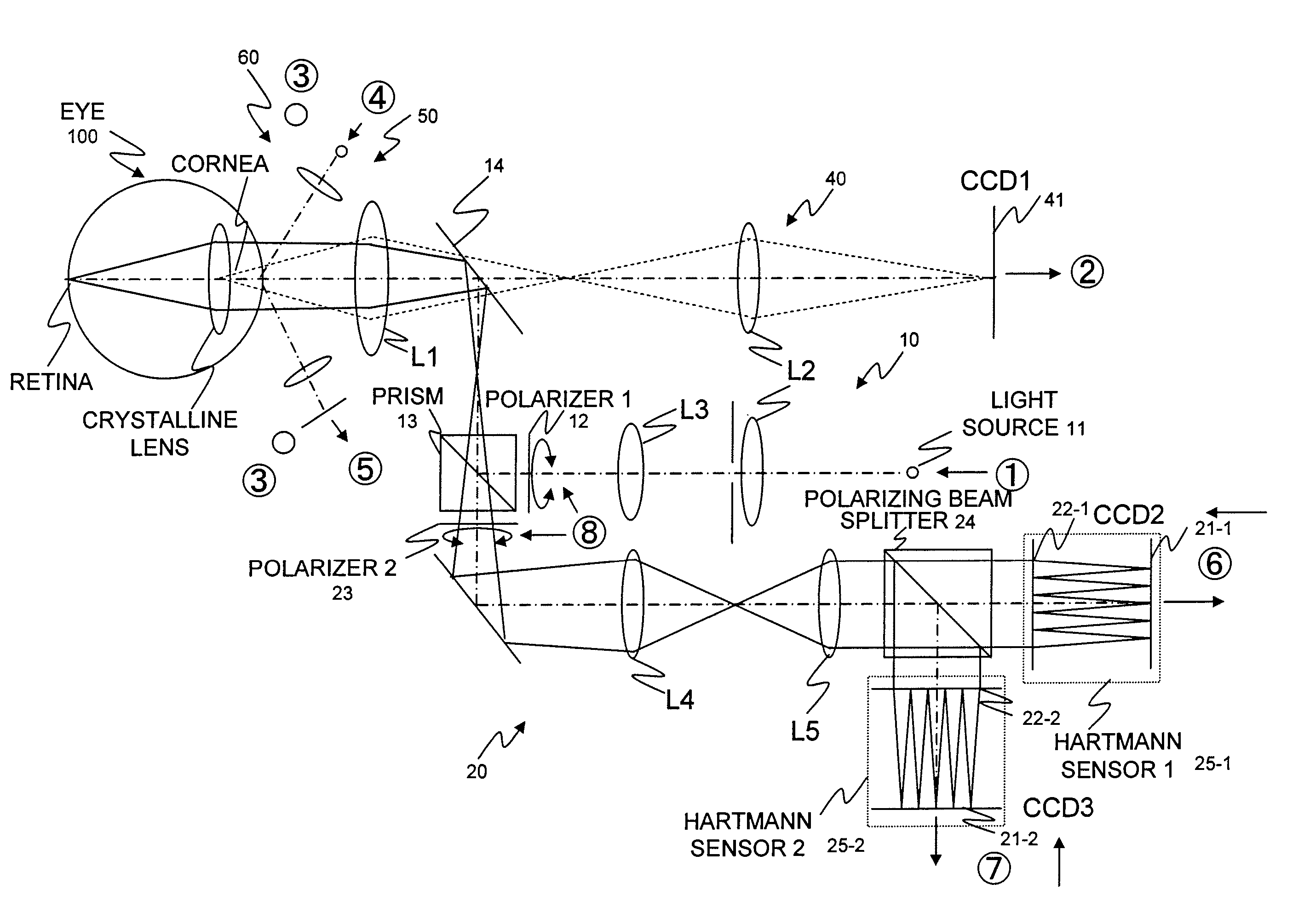
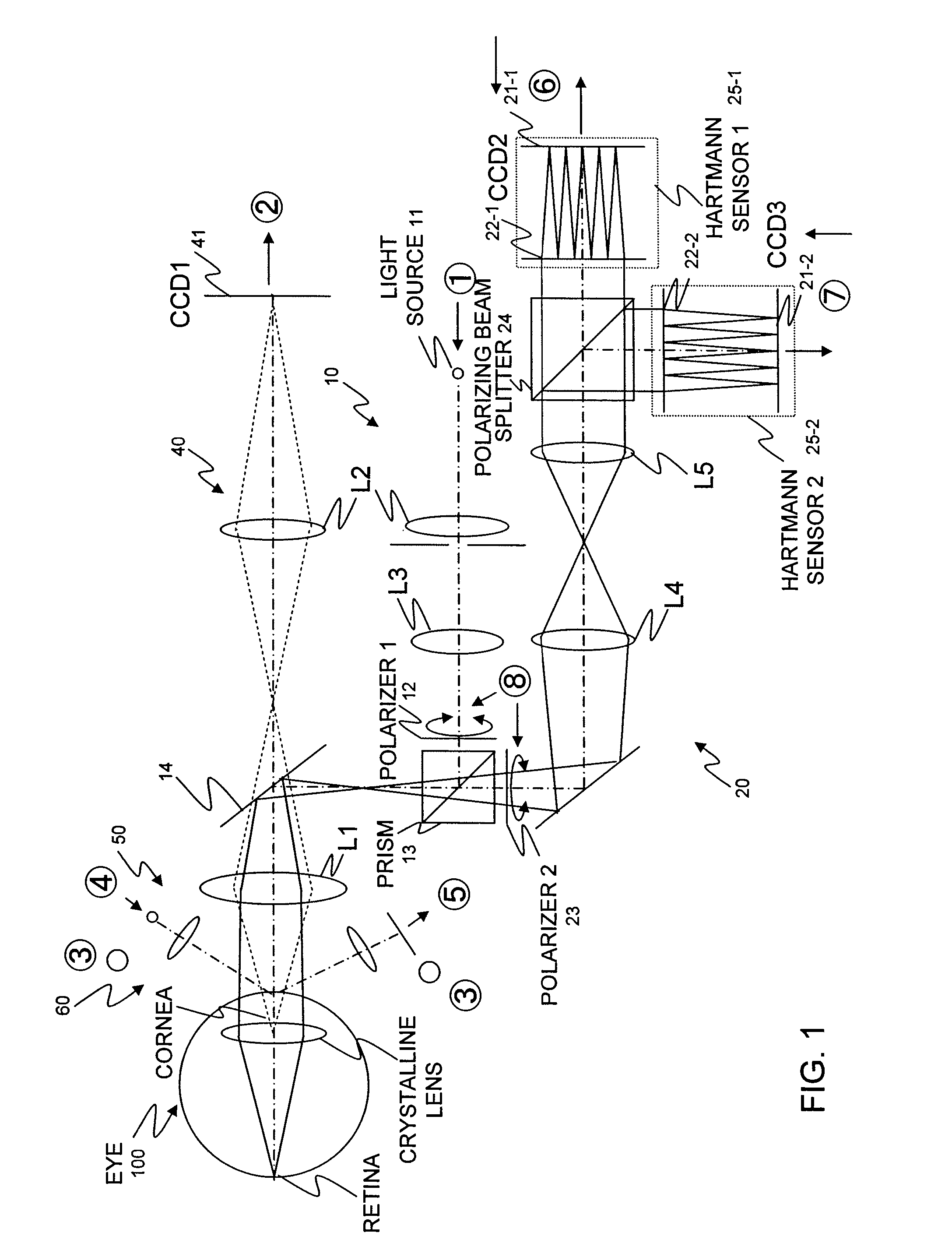
[0036]FIG. 1 is an optical arrangement view of an ophthalmologic measuring apparatus.

[0037]The apparatus includes a first illuminating optical system 10, a first light source part 11, a first light receiving system 20, an anterior eye observation part 40, a first adjustment optical part 50, and an anterior eye illumination part 60. Incidentally, with respect to a subject eye 100, a cornea (anterior eye part), a crystalline lens and a retina (ocular fundus) are shown.

[0038]The first light source part 11 emits light at a specified timing, and emits a light flux of a first wavelength. It is desirable that the first light source part 11 has high spatial coherence and not high temporal coherence. Here, as an example, an SLD (super luminescence diode) is adopted, and a point light source with high brightness can be obtained. Incidentally, the first light source part 11 is not limited to the SLD, and even if both the spatial and temporal coherences a...


PUM


Abstract

There is provided a Shack-Hartmann wavefront sensor which can repetitively perform a measurement at high speed and at short measurement intervals. An illuminating optical system includes a first polarizing optical member to alternately change a polarization condition to a first polarized light or a second polarized light, and illuminates a pulse light from a laser light source part to an ocular fundus of a subject eye through a first polarizing optical member. A light receiving optical system includes a second polarizing optical member to select each polarized light component of the reflected light from the subject eye illuminated according to the polarization condition of the first polarizing optical member, and a first and a second light receiving parts to alternately receive the reflected light of the selected polarized light component. An ophthalmologic measuring apparatus measures the wavefront aberration of the subject eye at short intervals based on the output of the first and the second light receiving parts.

Description

BACKGROUND OF THE INVENTION[0001]1. Field of the Invention[0002]The present invention relates to an ophthalmologic measuring apparatus, and particularly to an ophthalmologic measuring apparatus which can repeatedly perform a wavefront aberration measurement in a short time.[0003]2. Background Art[0004]Patent documents 1 and 2 disclose an ophthalmologic optical apparatus which measures a wavefront aberration of an eye by using two Shack-Hartmann wavefront sensors.[0005]In patent document 1, in FIG. 12 thereof, a first light receiving part and a third light receiving part correspond to a Shack-Hartmann wavefront sensor. However, their objects are different such that the first light receiving part receives a reflected light flux from a cornea to measure a cornea shape, and the third light receiving part receives a reflected light flux from a retina to measure optical characteristics.[0006]Patent document 2 discloses a structure in which reflected light from a retina is received by a lo...

Claims


Application Information

Patent Timeline
Patent Type & Authority Patents(United States)
IPC IPC(8): A61B3/10
CPCA61B3/1015
Inventor KOBAYASHI, MARIKOYAMAGUCHI, TATSUOMIHASHI, TOSHIFUMI
Owner KK TOPCON
Why Eureka
Try Eureka