Image color adjustment
a color adjustment and image technology, applied in the field of image color adjustment, can solve the problems of not being able to accurately reproduce the original colors, the distribution of colors of conventional color balancing, etc., and achieve the effect of higher quality and expressive freedom of images
- Summary
- Abstract
- Description
- Claims
- Application Information
AI Technical Summary
Benefits of technology
Problems solved by technology
Method used
Image
Examples
first embodiment
B. First Embodiment
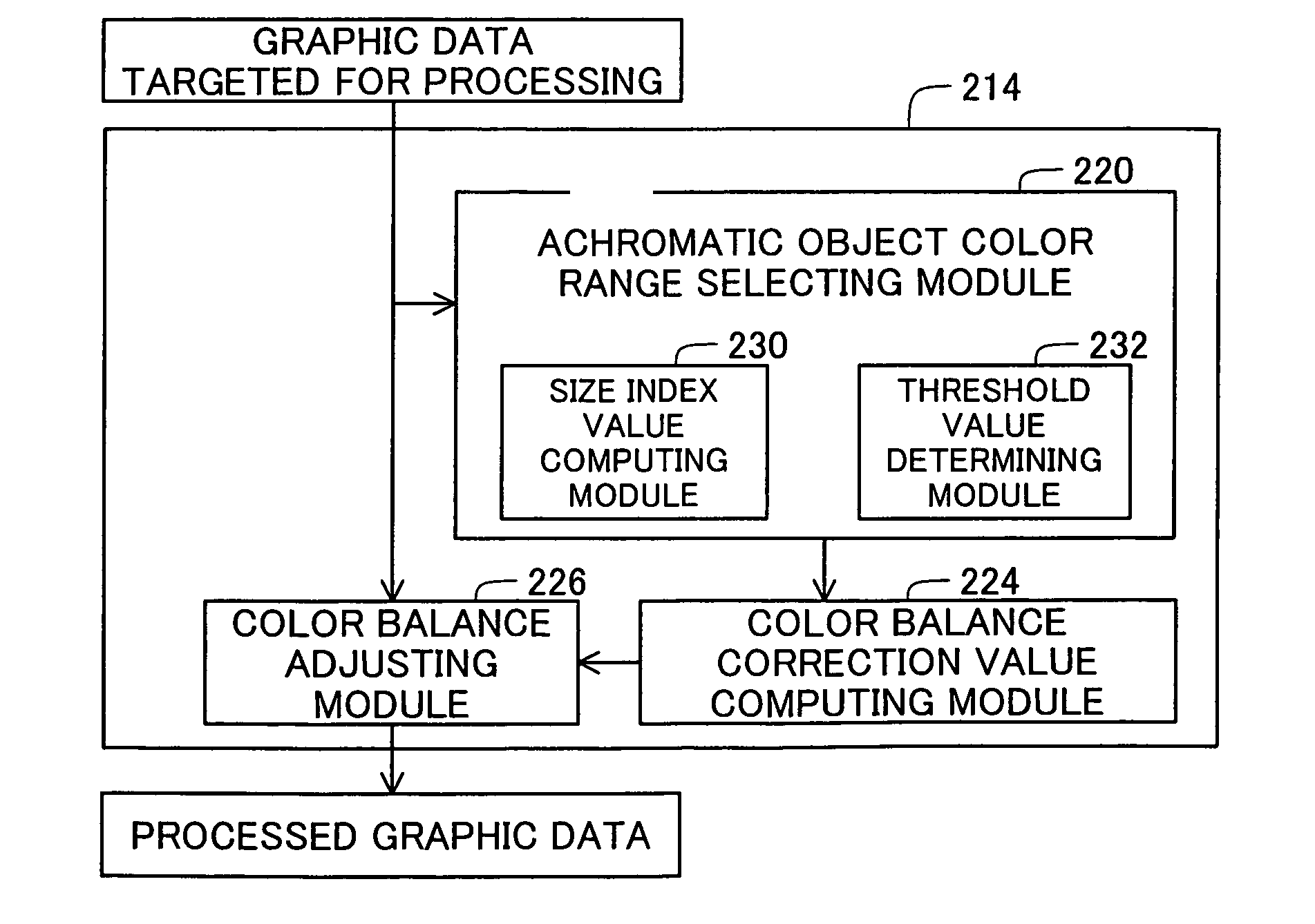
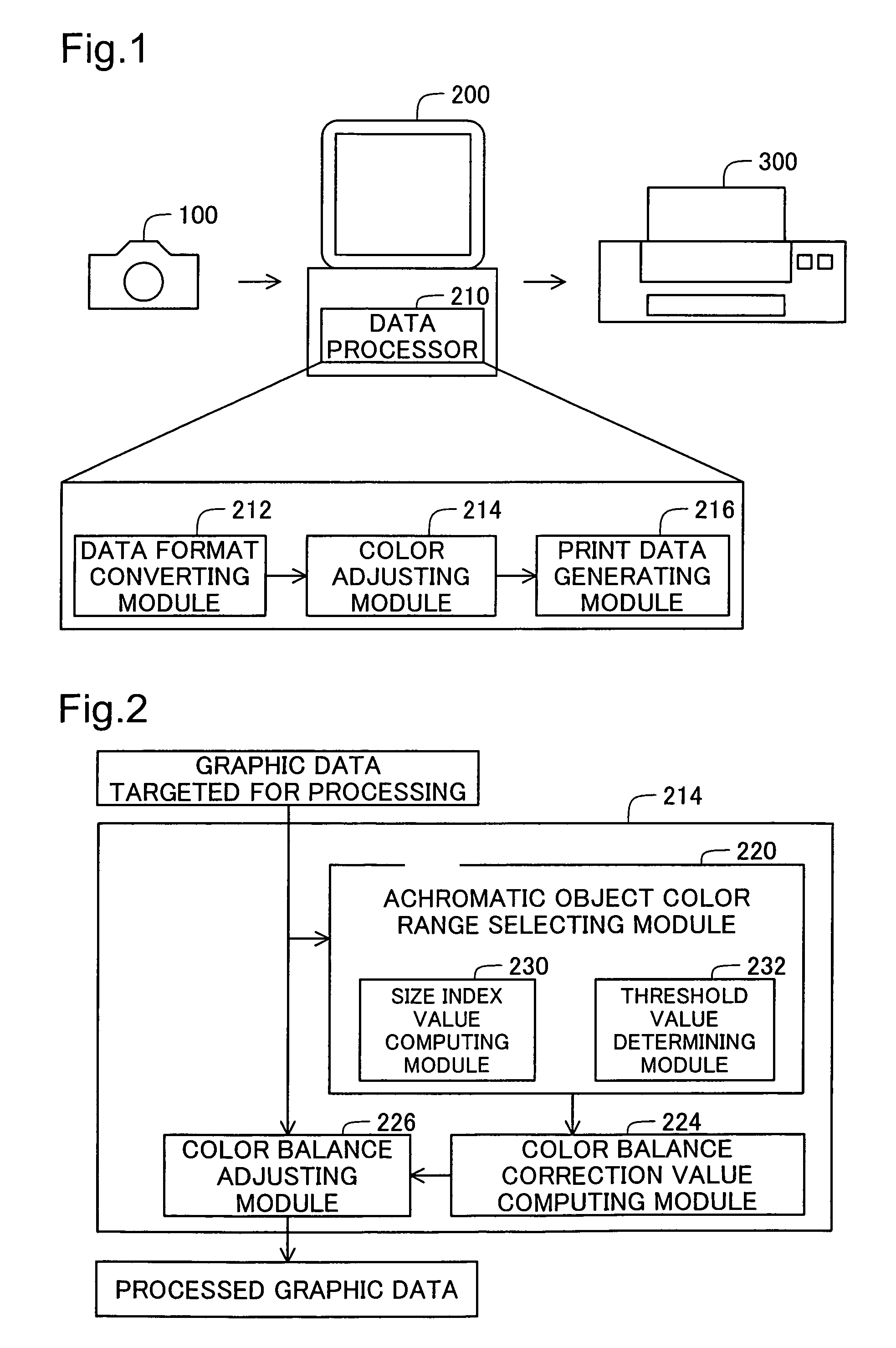
[0090]FIG. 2 is a block diagram of the internal structure of the color adjusting module 214 in the first embodiment. The color adjusting module 214 in the first embodiment comprises an achromatic object color range selecting module 220, color balance correction value computing module 224, and color balance adjusting module 226. The achromatic object color range selecting module 220 comprises a size index value computing module 230 and threshold value determining module 232. The color balance correction value computing module 224 and color balance adjusting module 226 correspond to the “color adjustment processing module” of the invention. In the first embodiment, the color adjusting module 214 adjusts the color balance of the image data targeted for processing.
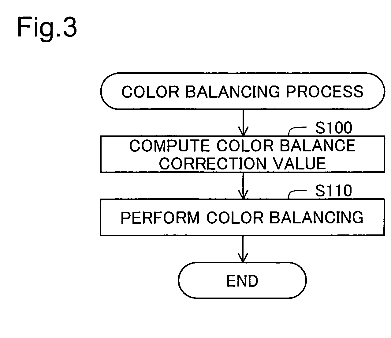
[0091]FIG. 3 is a flow chart of the procedure in the color balancing process of the color adjusting module 214 (FIG. 2). In Step S100, the achromatic object color range selecting module 220 (FIG. 2) selects ...
second embodiment
C. Second Embodiment
[0132]FIG. 8 illustrates details of color balancing in a second embodiment. The difference from the first embodiment shown in FIG. 7 is that tone curve correction is done for the RGB color components of the image data targeted for processing. The structure and operation are otherwise the same as in the first embodiment.
[0133]In the second embodiment, the color balance correction value computing module 224 uses the correction values (AWB_R, AWB_B, and AWB_G) calculated in the procedure described above to calculate the tone curve correction values ΔC(R), ΔC(G), and ΔC(B) according to the following Equations (4a) through (4c).
ΔC(R)=Ka×(AWB—R−1.0) (4a)
ΔC(G)=Ka×(AWB—G−1.0)=0.0 (4b)
ΔC(B)=Ka×(AWB—B−1.0) (4c)
[0134]Here, Ka is a certain coefficient. The tone curve correction values ΔC(R), ΔC(G), and ΔC(B) denote the extent of correction by which an output value for a reference input value Dref is corrected from the non-correction properties. The average luminance value...
third embodiment
D. Third Embodiment
[0137]FIG. 9 is a block diagram of the internal structure of the color adjusting module 214a in the third embodiment. This differs in two ways from the first embodiment shown in FIG. 2. One difference is that a color conversion matrix selecting module 222a and color converting module 223a are provided instead of the color balance correction value computing module 224 and color balance adjusting module 226. Another difference is that the processing details of the achromatic object color range selecting module 220a are different from those of the achromatic object color range selecting module 220 in the first embodiment. Unlike the first embodiment in FIG. 2, the color adjusting module 214a executes a color conversion process on the image data targeted for processing. The structure and operation are otherwise the same as in the first embodiment. The color conversion matrix selecting module 222a and color converting module 223a also correspond to the “color adjustmen...
PUM
 Abstract
Description
Claims
Application Information
 - R&D
- Intellectual Property
- Life Sciences
- Materials
- Tech Scout
- Unparalleled Data Quality
- Higher Quality Content
- 60% Fewer Hallucinations
Browse by: Latest US Patents, China's latest patents, Technical Efficacy Thesaurus, Application Domain, Technology Topic, Popular Technical Reports.
© 2025 PatSnap. All rights reserved.Legal|Privacy policy|Modern Slavery Act Transparency Statement|Sitemap|About US| Contact US: help@patsnap.com


