
Command inflatable boat stopping barrier

a technology for inflatable boats and occupants, which is applied in the direction of special-purpose vessels, water cleaning, vessel construction, etc., to achieve the effect of high friction coefficient, without excessive damage to the boat or injury to its occupants

Inactive Publication Date: 2009-12-29
USA AS REPRESENTED BY THE SEC OF THE NAVY THE
View PDF4 Cites 18 Cited by
  • Summary
  • Abstract
  • Description
  • Claims
  • Application Information

AI Technical Summary

Benefits of technology

[0008]The present invention provides an inflatable barrier system capable of diverting an approaching boat without inflicting excessive damage to the boat or injury to its occupants. A barrier support platform houses a pressurized gas source and a power supply and has a winch connected to a pair of cables. An inflatable barrier body member having a bow and stern is coupled to the pressurized gas source for inflation of the body member, and the cables are connected to the bow and stern to deploy the inflated body member at the surface of the water and to maintain the bow above the surface and the stern below the surface of the water. A barrier controller provides signals indicative of the approaching boat to initiate the inflation of the inflatable barrier body member and the deployment of the inflated barrier body member at the surface with the bow above the surface and the stern below the surface. An acoustic modem / signal receiver is also housed in the support platform and is responsive to the signals indicative of the approaching boat on the water's surface. Control electronics are also housed in the support platform and are responsive to the acoustic modem / signal receiver to actuate the gas source and the winch. The inflatable barrier body member has an inflatable chamber and is wedge shaped when the chamber is inflated by pressurized gas. A deflating valve is connected to the body member to allow its selective deflation and a one-way inflation valve fitting is connected to the body member to receive and pass pressurized gas from the pressurized gas source to the inflatable chamber. The body member has tough flexible walls of a heavy-duty laminate structure enclosing an inflatable chamber. A topside surface layer of thick, tough, rough textured material is disposed on the body member and has a very high friction coefficient to arrest forward progress and to keep the broached boat from sliding backward off the inflated body member.
[0012]Another object of the invention is to provide an inflatable barrier system having a ramp-shaped inflatable barrier body member to divert / stop motion of a boat with low impact to reduce the possibility of boat damage and / or injury to its occupants.

Problems solved by technology

To be successful, however, the boat or small craft must be willing to stop for closer inspection; if this isn't accomplished, the intercepting craft would have to use destructive force to engage the intruder with the danger of receiving hostile fire in return.

Method used


Image

  • Command inflatable boat stopping barrier
  • Command inflatable boat stopping barrier
  • Command inflatable boat stopping barrier

Examples


Embodiment Construction

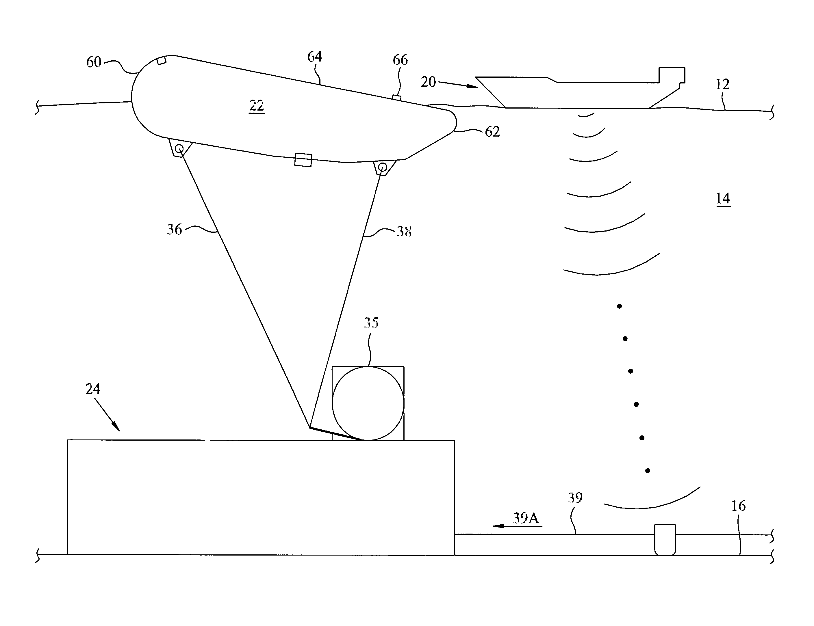
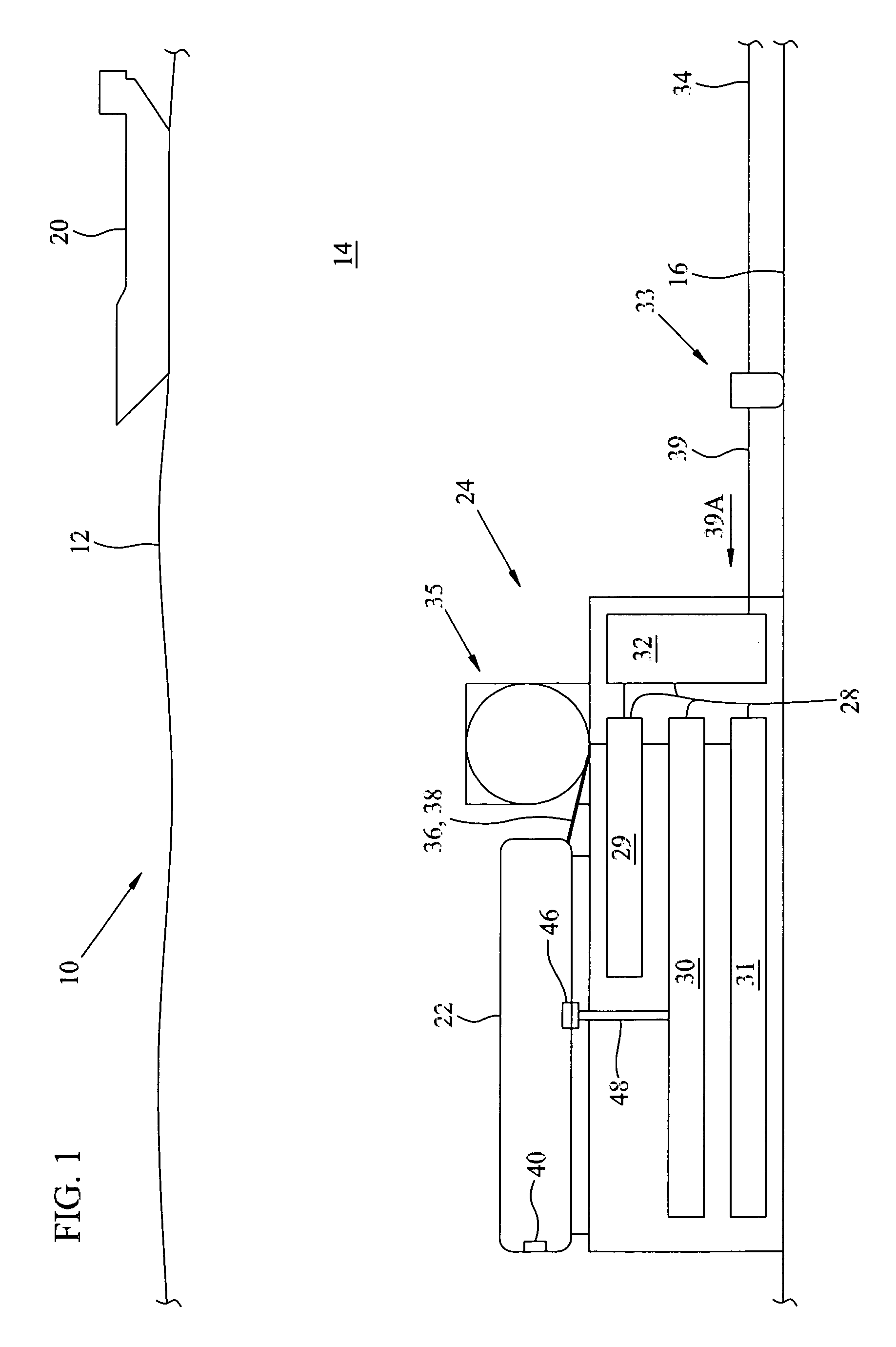
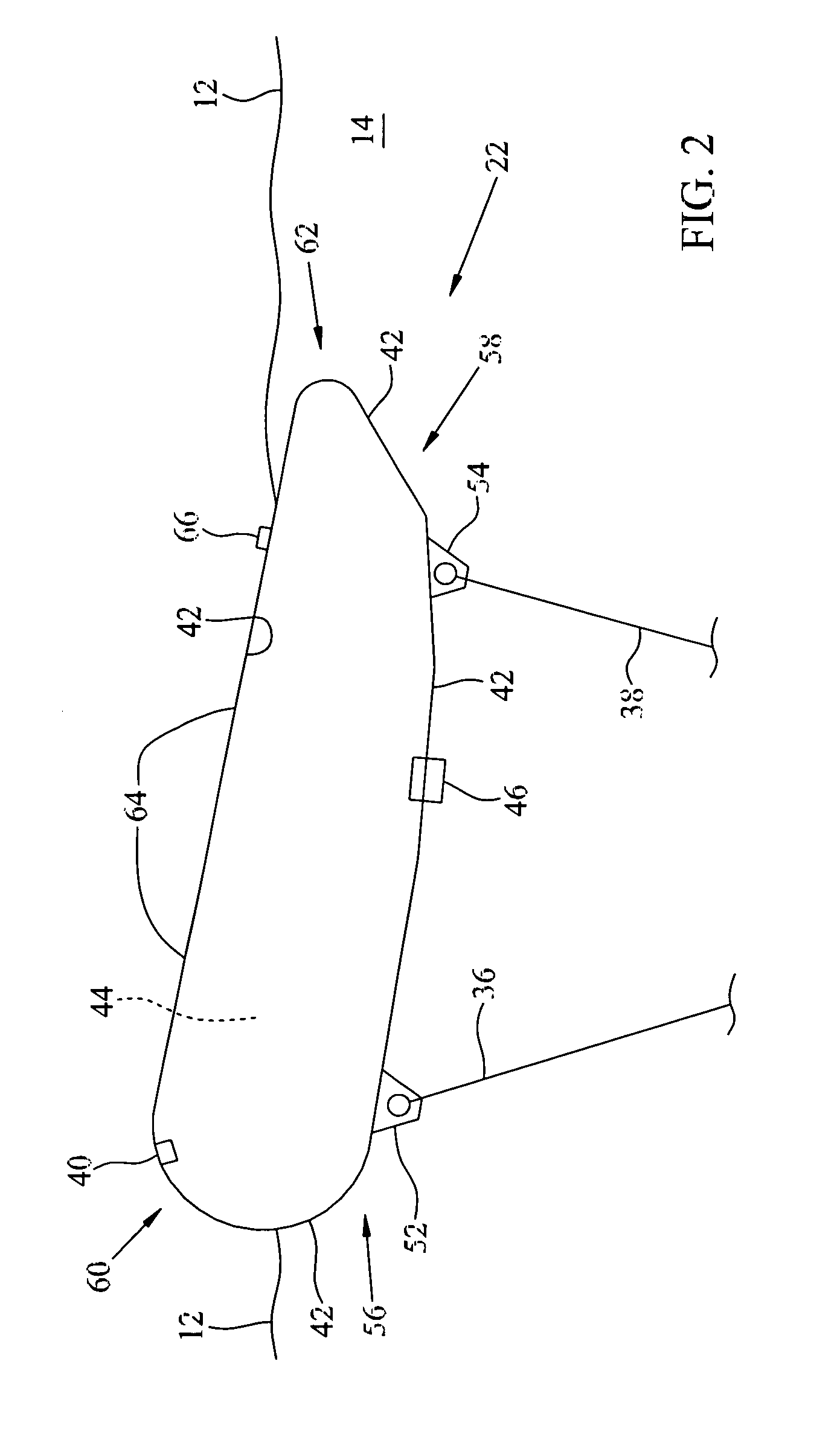
[0020]Referring to FIG. 1, an inflatable barrier system 10 of the invention is submerged below the surface 12 of a body of water 14 on the bottom 16. Alternatively, the system can be moored above the bottom while remaining concealed below surface 12. Barrier system 10, therefore, is hidden from view by personnel on an approaching boat or other small craft 20 until a flexible inflatable barrier body member 22 is inflated on a barrier support platform 24 and is deployed to surface 12 to arrest the motion of boat 20.

[0021]Barrier support platform 24 preferably has a heavy duty metal construction that may be additionally negatively ballasted to function as a heavy sea anchor-enclosure or housing for barrier system 10 that holds it on the bottom when inflatable barrier body member 22 on platform 24 is inflated. The robust construction of platform 24 allows it to be quickly placed on bottom 16 at short notice by expeditiously dropping it into water 14 from a boat or low flying aircraft. P...


PUM


Abstract

An inflatable barrier system halts an approaching boat. A barrier support platform houses a pressurized gas source and a power supply and has a winch connected to a pair of cables. An inflatable barrier body member having a bow and stern is coupled to the pressurized gas source for inflation of the body member and the cables are connected to the bow and stern to deploy the inflated body member at the surface of the water and to maintain the bow above the surface and the stern below the surface of the water. A barrier controller provides signals indicative of the approaching boat to initiate the inflation of the inflatable barrier body member and the deployment of the inflated barrier body member at the surface with the bow above the surface and the stern below the surface without inflicting excessive damage to the boat or injury to its occupants.

Description

STATEMENT OF GOVERNMENT INTEREST[0001]The invention described herein may be manufactured and used by or for the Government of the United States of America for governmental purposes without the payment of any royalties thereon or therefor.BACKGROUND OF THE INVENTION[0002]This invention is for a quickly deployable barrier for boats. More particularly, this invention provides a non-visible, submerged ramp-shaped flotation barrier selectably released and inflated to non-lethally and non-destructively divert or stop forward progress and navigability of boats to secure an area.[0003]Usually manned patrol craft or aircraft are sent to intercept potentially hostile boats or small water craft intruding in a restricted water area. To be successful, however, the boat or small craft must be willing to stop for closer inspection; if this isn't accomplished, the intercepting craft would have to use destructive force to engage the intruder with the danger of receiving hostile fire in return.[0004]...

Claims


Application Information

Patent Timeline
IPC IPC(8): B63B7/00
CPCB63C3/02F41H11/05B63G9/04B63G9/00B63G8/001
Inventor PORTMANN, HELMUTMORITZ, ELANEVERHART, DAVIDSWART, RONALD
Owner USA AS REPRESENTED BY THE SEC OF THE NAVY THE
Learn More