Compactly foldable skywatcher's tripod

a tripod and folding technology, applied in the field of skywatching equipment, can solve the problems of putting a strain on one's back, limiting the dynamic use of acquiring and tracking a moving target, and conventional tripods not serving this mark

Inactive Publication Date: 2009-12-29
CIRAMI SALVATORE
View PDF21 Cites 12 Cited by
  • Summary
  • Abstract
  • Description
  • Claims
  • Application Information

AI Technical Summary

Benefits of technology

[0052]The seat support member has a rearward end portion that extends outboard of the base when the seat support member is in its unfolded position parallel to the main member. A handle is fixed to an underside of this rearward end portion of the seat support member, the handle being attached such that when the seat support member is in its unfolded position the handle is in a storage position depending from the seat support member, the rearward end portion of the seat support member extending far enough outboard of the base that the handle hangs spaced above the leg members when the leg members are in their unfolded position so that there is no interference therebetween. The handle has a length such that (a) when the seat is in its folded position standing against the post member, and (b) the rider support is centered between two leg members so that the rearward end of the main member is thereby aligned with the third one of the leg members, and (c) the third leg member is in its folded position standing upright parallel to the swivel axis, a free end of the handle is substantially in abutment with the said third leg member, with the result that the third leg member prevents unfolding of the seat from its upright storage position while at the same time holding the handle in its usable position for carrying the tripod.
[0053]Finally, other objects of the present improvement are (a) to provide the elevation of the extended extension arm lockable by a means that takes into account the significant weight of the surveillance device that may be carried, and (b) to provide a swivel lock means that can be applied virtually instantaneously so that the surveillance device can immediately be stopped on a target that suddenly makes its appearance, and which can be applied while the user continues to sight through the surveillance device.

Problems solved by technology

The conventional tripod commonly used for support of a telescope, binocular, camera, etc., is fine for training on a relatively stationary target such as a star but is severely limited for dynamic use acquiring and tracking a moving target such as a bird, airplane or unidentifiable object which may circle the observer's position and even pass overhead.
The conventional tripod does not serve this market.
Conventionally one stands behind the tripod with limited ability to pan the horizon, which can be boring and a discouragement to the casual skywatcher, and usually requires bending over to sight through a substantially straight line-of-sight surveillance device such as a binocular, which puts a strain on one's back.
This may make the tripod top-heavy, and if the user is standing, the column may not be raisable high enough for accessing the surveillance device's eyepiece without crouching, and close placement of a chair for sitting under the surveillance device is limited by interference with the tripod's legs and further restricts panning.
Besides being inconvenient with respect to the number of separate pieces of equipment which must be carried to the viewing site, this recourse still does not permit the user to swing about the horizon looking for a subject of interest; in order to do that he will have to step around the tripod (with risk of tripping on its legs) while repositioning the boom and the chair.
Compensating for these limitations telescopes and spotting scopes are available having their eyepiece fixed at or adjustable to a 45 or 90 degree angle relative to the line-of-sight of the device so that the user need not tilt his head so for backward in order to look overhead, but such offset viewing is counter-intuitive, especially for the occasional user, and therefore a handicap when one is trying to quickly acquire a moving target.
This approach has proven impractical due to problems having to do with confinement of the seated skywatcher, obstruction of peripheral vision and proper alignment of the surveillance device's eyepiece with the user's eyes at different elevations of the surveillance device, as well as excessive weight due to complexity adversely affecting hand-carried portability or requiring assembly of parts at the skywatching site.
While this approach solves the problem of unsteadiness, the tripod itself usually interferes with the position that the body of the user must assume when viewing objects at an angle of altitude from the horizon.
Furthermore, few tripods are sufficiently tall enough to position the binoculars high enough for a tall user, when the user is looking up from a standing position.
Through [sic] this apparatus is apparently of considerable utility, the photograph itself shows a principal disadvantage of such devices, as the user leans forward awkwardly from the stool to bring his eyes to the appropriate distance from the fixed tripod.
Presumably the stool could be moved to a better position for at least some viewing angles; however, the picture also suggests another drawback—namely, that movement of the stool (or of the user's position if standing) is required to change the vertical viewing angle.
“Most of the tripods and chair brackets discussed above are difficult to adjust when changing viewing angles.
This tendency is badly aggravated by the requirement that while viewing the user keep his body in practically the same position relative to the tripod or chair.
“Fifth and finally, all of the tripod and chair-bracket systems—even those of Mandler, Riggs and Leifer—are limiting in that their size and in some cases their weight inhibit the user's freedom of movement.”
These back issues of Sky and Telescope magazine are no longer available for purchase and so the articles referred to in the Wong patent have not been directly examined and any photograph or illustration provided therein has not been seen by the instant inventor.
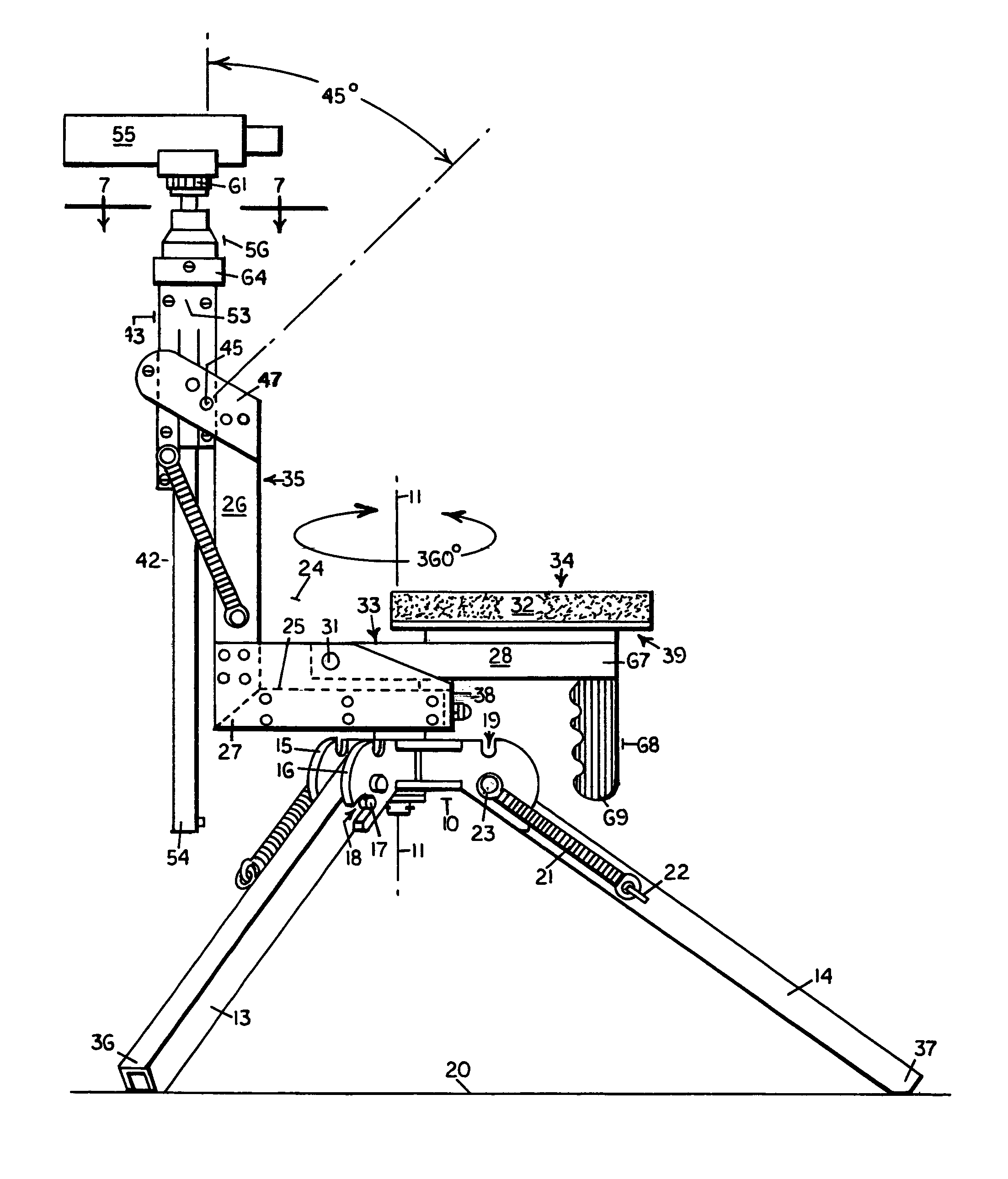
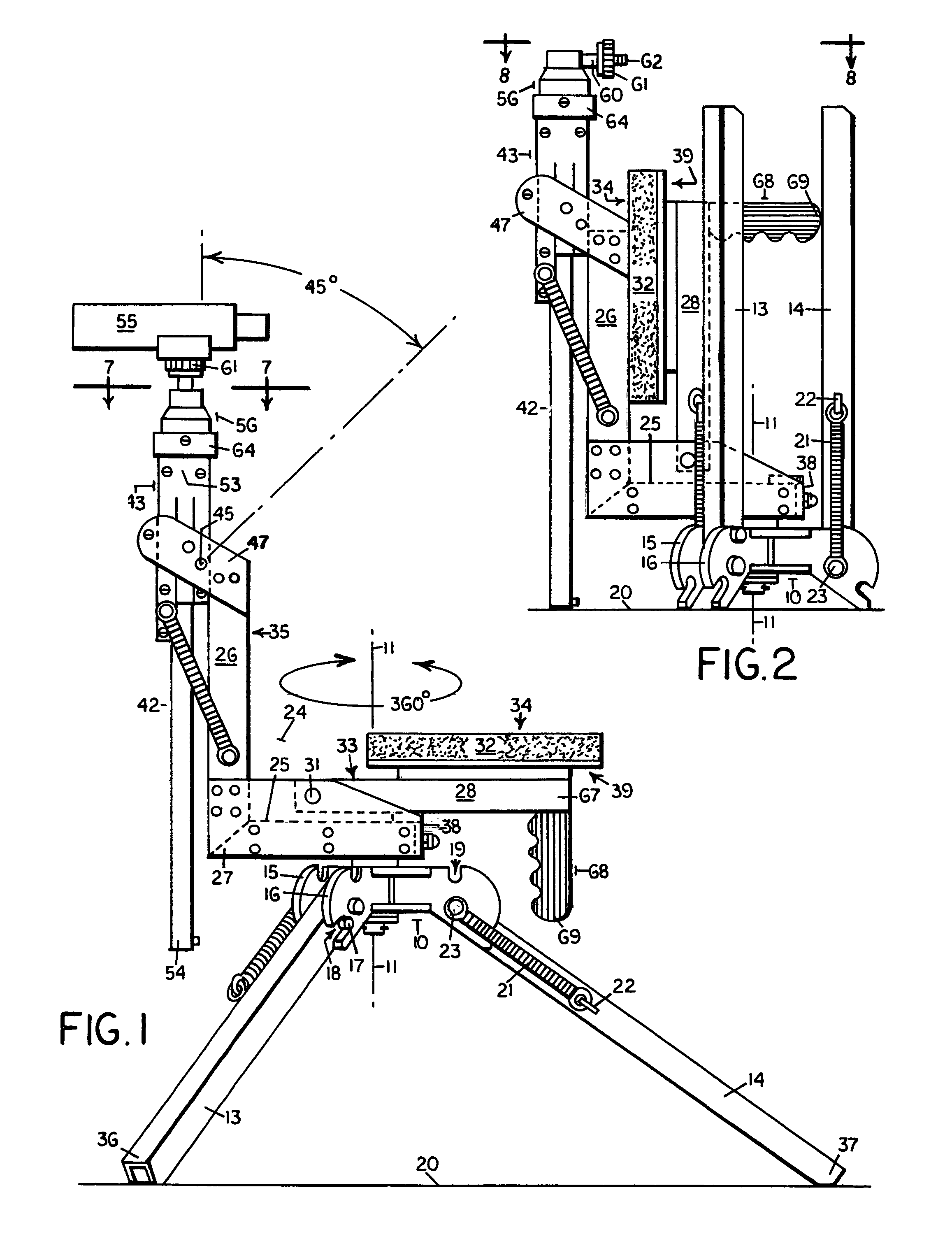
The material quoted above shows that the prior approach has been to provide the surveillance device mounted on an arm structure that rises from behind the seated user, usually attached to a backrest, and to have such arm structure extending over or around the user, resulting in the undesirable sense of confinement discussed above.

Method used


Image

  • Compactly foldable skywatcher's tripod
  • Compactly foldable skywatcher's tripod
  • Compactly foldable skywatcher's tripod

Examples


Embodiment Construction

[0064]Referring to the accompanying drawings, a skywatcher's tripod according to the present improvement includes prior art comprising a base, indicated generally as 10, FIGS. 1 and 10, defining a swivel axis 11, three leg members 12, 13, 14, FIG. 10, pivotally secured to the base 10 for rotation about leg pivot axes 12′, 13′, 14′, respectively, FIGS. 8 and 10, which are orthogonal to the swivel axis 11, the base 10 including three pairs of parallel spaced apart base lugs as at 15, 16, in FIGS. 1 and 2, between which the leg members, such as leg member 13 in FIG. 1, are secured. Each leg member includes a pin as at 17, FIG. 1, that is received in notches as at 18 (associated with leg member 13) and 19 (associated with leg member 14), which are formed in each pair of base lugs, whereby the leg members are securable in an unfolded position as shown in FIG. 1 wherein the leg members are positioned inclined downwardly from the base 10 in order to support the base 10 at an elevation spac...


PUM


Abstract

A skywatcher's tripod has a seat mounted on a rider support that swivels 360 degrees on a base having upwardly foldable tripod legs. A post forms a forward end of the rider support. An extension arm configured to secure a tripod head for attachment of a surveillance device is axially slidable in a holder that is pivotally secured to the upper end of the post for rotation towards the seated user. The user sights on targets from horizon to zenith depending on the rotated position of the holder and the extension of the arm. The seat folds against the post outboard of the folded tripod legs and is held in folded position by a folded leg that abuts a handle that extends from a bottom side of the seat. The rider support includes a swivel lock and a combination holder/extension arm lock.

Description

CROSS-REFERENCE TO RELATED APPLICATION[0001]This disclosure is a Continuation-in-Part filed with an original application Ser. No. 11 / 483,363 filed Jul. 10, 2006, now abandoned. Benefit of earliest filing date is claimed for common subject matter.STATEMENT REGARDING FEDERALLY SPONSORED RESEARCH OR DEVELOPMENT[0002]Not applicable.THE NAMES OF THE PARTIES TO A JOINT RESEARCH AGREEMENT[0003]Not applicable.INCORPORATION-BY-REFERENCE OF MATERIAL SUBMITTED ON A COMPACT DISC[0004]Not applicable.BACKGROUND OF THE INVENTION[0005]1. Field of the Invention[0006]This invention pertains to skywatching apparatus used to provide a steady support for a surveillance device such as a binocular, telescope, camera or camcorder.[0007]2. Background Art[0008]The conventional tripod commonly used for support of a telescope, binocular, camera, etc., is fine for training on a relatively stationary target such as a star but is severely limited for dynamic use acquiring and tracking a moving target such as a bi...

Claims


Application Information

Patent Timeline
Patent Type & Authority Patents(United States)
IPC IPC(8): A47C1/12A47C4/00A47C7/62
CPCA47C9/00A47C7/62
Inventor CIRAMI, SALVATORE
Owner CIRAMI SALVATORE
Why Eureka
Try Eureka