Articulated endoprosthesis

a technology of endoprosthesis and articulation, which is applied in the field of joint, can solve the problems of no body fluid, possible chemical attack on parts of the implant, and impaired service life of the implant, and achieve good lubricating qualities

Active Publication Date: 2009-12-29
SYNTHES USA
View PDF16 Cites 9 Cited by
  • Summary
  • Abstract
  • Description
  • Claims
  • Application Information

AI Technical Summary

Benefits of technology

[0015]Thus the present invention allows the provision of one or a plurality of channels terminating in the boundary surfaces between the implant and the bones, said channels being suitable to supply body fluids, containing proteins and other substances with good lubricating qualities, to the articular surfaces mounted superposed in a sliding manner.
[0015]Thus the present invention allows the provision of one or a plurality of channels terminating in the boundary surfaces between the implant and the bones, said channels being suitable to supply body fluids, containing proteins and other substances with good lubricating qualities, to the articular surfaces mounted superposed in a sliding manner.
[0012]In further embodiment the articular surfaces of the joint parts are produced from material pairs of metal / polymer, metal / metal or ceramics / ceramics.

Problems solved by technology

The articular surfaces remain usually dry, due to which the service life of the implant may be impaired.
A disadvantage of this implant is that the fluid chamber is enclosed, so that no body fluid can be absorbed from outside the chamber.
Due to lack of circulation the pH value of this accumulated fluid may drop, resulting in a possible chemical attack on parts of the implant.
In addition, the enclosed fluid chambers, which are connected with the external surfaces of the implant through such fissures, may exhibit an undesirable pumping effect caused by the relative movements of the parts of the implant.

Method used


Image

  • Articulated endoprosthesis
  • Articulated endoprosthesis
  • Articulated endoprosthesis

Examples


Embodiment Construction

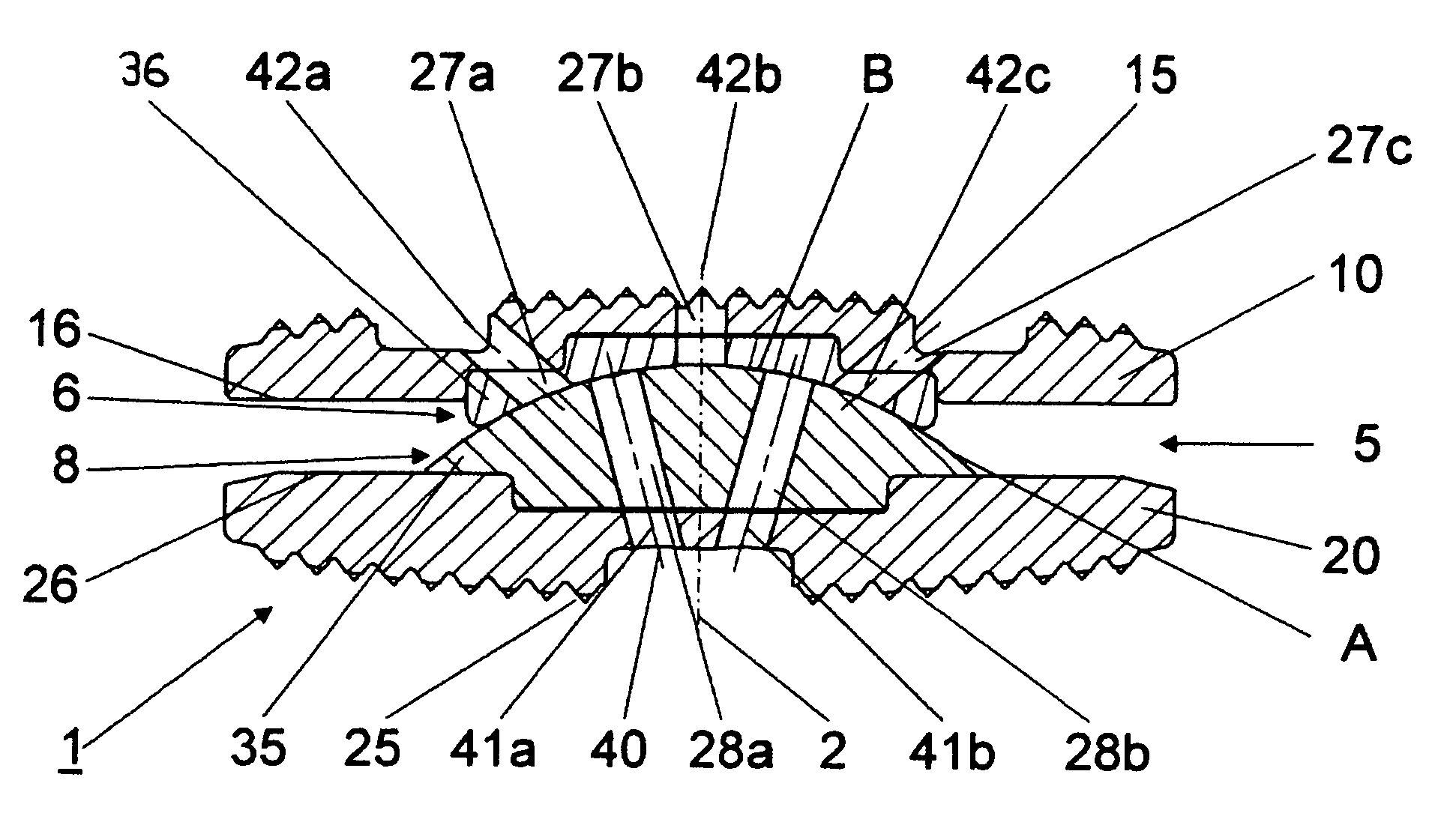
[0023]In FIG. 1 a medio-laterally sectioned embodiment of the endoprosthesis for a joint for an intervertebral implant 1 is illustrated. The intervertebral implant 1 illustrated in FIG. 1 comprises a top part 10 and a bottom part 20, which enclose a joint 5 and are axially superimposed relative to central axis 2 that is substantially parallel to the longitudinal axis of the spine. The top part 10 has a top apposed surface 15 for the purpose of placing it adjacent a vertebra located above The top apposed surface 15 axially protrudes and is substantially perpendicular to the central axis 2. The top part 10 also has a bottom inside surface 16 preferably with an integrated top joint part 6.

[0024]Analogously to that, the bottom part 20 has a bottom apposed surface 25 for the purpose of placing it adjacent a vertebra located below. The bottom apposed surface 25 axially protrudes and intersects the central axis 2. The bottom part 20 also has an inside top surface 26 preferably with the int...


PUM

PropertyMeasurementUnit
angleaaaaaaaaaa
angleaaaaaaaaaa
diameteraaaaaaaaaa

Abstract

An endoprosthesis for a joint, in particular a an intervertebral implant with a central axis, a top part, a bottom part and a joint provided between them, wherein the joint comprises at least two articular surfaces A and B that can slide on one another; the top part has a top apposed surface that intersects the central axis and lateral surfaces; the bottom part has a bottom apposed surface that intersects the central axis and lateral surfaces; and wherein the endoprosthesis comprises at least one channel suitable to convey body fluid, said channel terminating in one of the two articular surfaces A and B and connecting it with the exterior of the endoprosthesis for the joint.

Description

CROSS-REFERENCE TO RELATED APPLICATION[0001]This application is a continuation of International Patent Publication PCT / CH2003 / 000494, filed Jul. 22, 2003, which is incorporated by reference herein in its entirety.FIELD OF THE INVENTION[0002]The present invention relates to an joint, in particular to an endoprosthesis and most particularly to an artificial intervertebral implant.BACKGROUND OF THE INVENTION[0003]Most intervertebral implants or intervertebral disk prosthesises used currently comprise a joint, the articular surfaces of which are made from metal, polymers or ceramic materials. The articular surfaces remain usually dry, due to which the service life of the implant may be impaired. In addition, due to the limited rotational movement of the parts of the joint, mounted superposed in a sliding manner, the tribological properties are of importance.[0004]EP-B 0 193 538 to Marnay et al. discloses an artificial acetabulum that is fitted with a fluid chamber to improve the tribolo...

Claims


Application Information

Patent Timeline
Patent Type & Authority Patents(United States)
IPC IPC(8): A61F2/44A61F2/00A61F2/30B01D61/02B01D61/10C02F1/44F04F5/54
CPCA61F2/4425F04F5/54B01D61/02B01D61/022B01D61/10A61F2002/30364A61F2002/30369A61F2002/30637A61F2002/30649A61F2002/30673A61F2002/30892A61F2002/443A61F2220/0033A61F2002/30843A61F2002/30624B01D61/026A61F2/44A61F2/30
Inventor LECHMANN, BEATBURKI, ROGERBURKARD, DOMINIQUEFRIGG, ROBERTODERMATT, DANIEL
Owner SYNTHES USA
Why Eureka
Try Eureka